Acrob technical description: Rozdiel medzi revíziami
Zo stránky SensorWiki
dBez shrnutí editace |
|||
| Riadok 19: | Riadok 19: | ||
Obrázok:AcrobPcb_B.png|''pcb B'' | Obrázok:AcrobPcb_B.png|''pcb B'' | ||
Obrázok:AcrobMechanic.png|''radiator mech'' | Obrázok:AcrobMechanic.png|''radiator mech'' | ||
Obrázok:acrobISPconnector.png|''ISP connector'' | |||
</gallery> | </gallery> | ||
Verzia z 08:24, 23. február 2025
Documentation

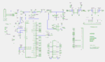
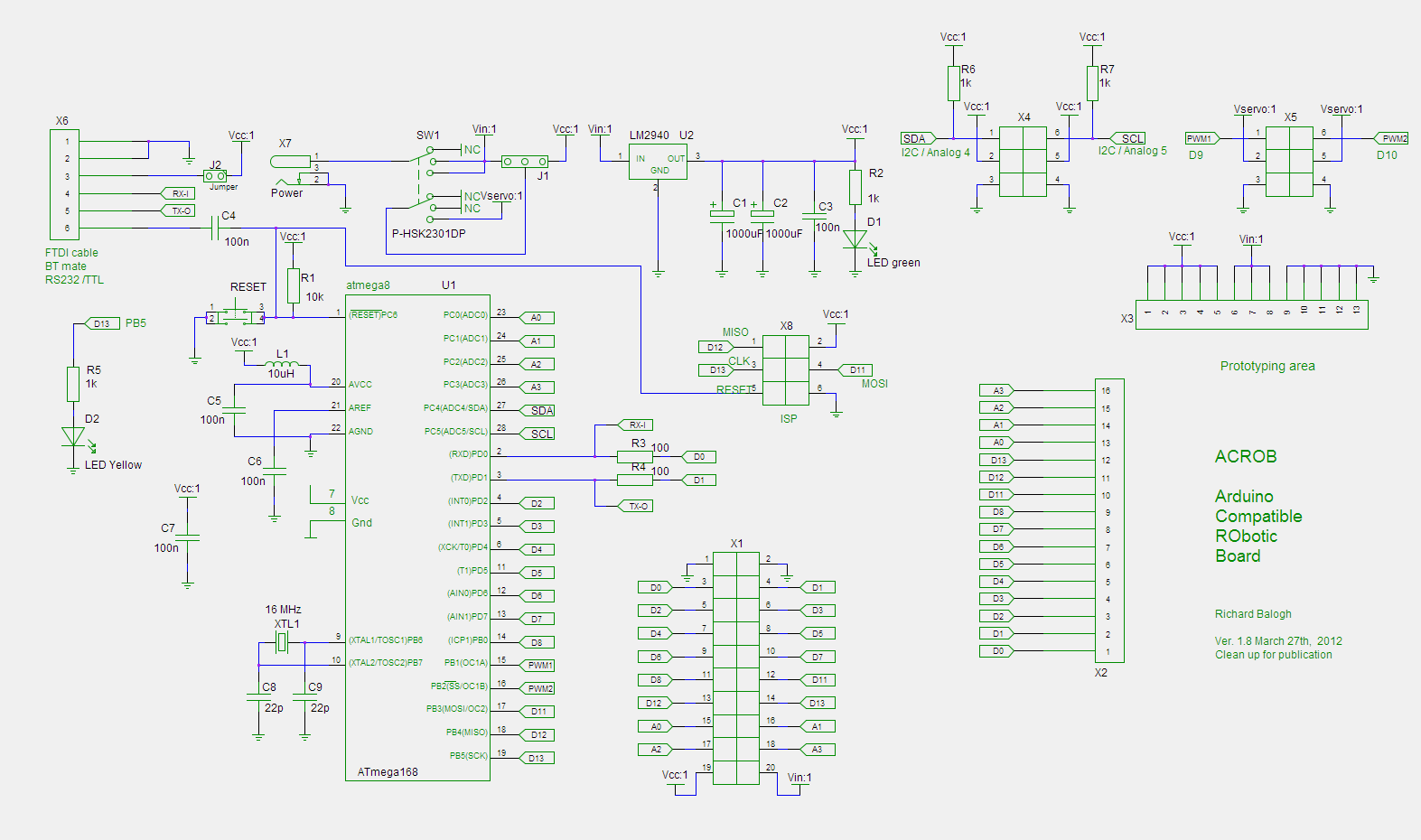
- Schematic diagram
- List of components
- The board description
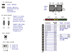
- Connectors, pinouts, jumpers
- Resources
-
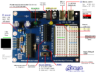 The Board
 -
-
-
 pcb A
pcb A -
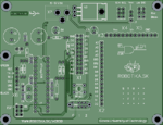
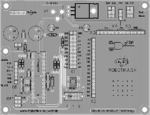 pcb B
pcb B -
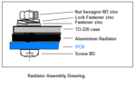 radiator mech
 -
ISP connector


Sources

Acrob board is open hardware. Schematic diagram and final pcb were designed
using the gEDA suite of programs.
Here you can find all the necessary source files to produce the boards:
- Schematic diagram: (gEDA .sch, .pdf, .png)
- Printed circuit board (gEDA .pcb)
- Gerber files (.zip)
- Tools used: gEDA suite
Information and Links
- Arduino
- Language Reference
- Robotics with Boe-Bot Robot (BasicStamp)
Components
- ATmega328 Description + Datasheet
- FTDI Basic Breakout board
- LM2940-5.0 Description + Datasheet
Tips and troubleshooting
- Note: configuring Reset in Windows - http://www.arduino.cc/en/Guide/ArduinoPro
