CADRS Cvičenie 10
Z SensorWiki

Obsah
16-bitové počítadlo a časovač T1 s prerušením
Literatúra:
- Newbie's Guide to AVR Timers
- The traps when using interrupts
- Ako používať časovače v AVR C
- Prednáška o prerušeniach (Ing. Chamraz)
Rekapitulácia
Máte k dispozícii vývojovú dosku MiniMEXLE (popis,schéma zapojenia) a s procesorom ATmega88 (datasheet) a prípadne aj testovací program mexletest2.hex.
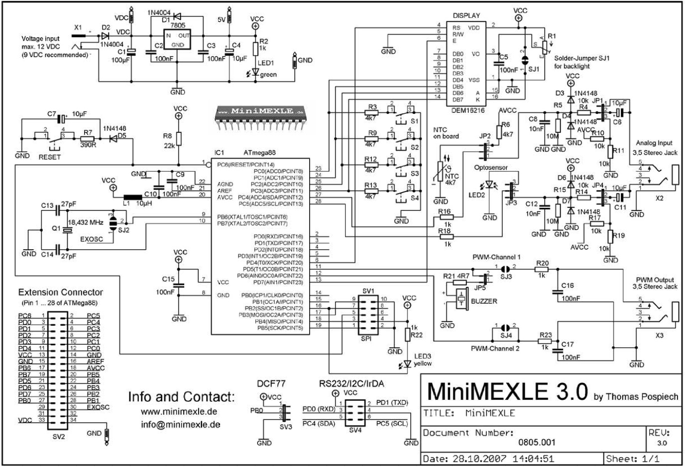
V tejto úlohe sa predpokladá znalosť funkcie časovača T1 z prednášky (datasheet, str. 87 -- 115).
Procesor je nakonfigurovaný na prácu s externým kryštálovým oscilátorom 18,432 MHz (fuses).
Demonštračný program je tuto: mexletest9.hex
Časovač T1
Pozri AVR ExampleT1pooled.c
Úlohy
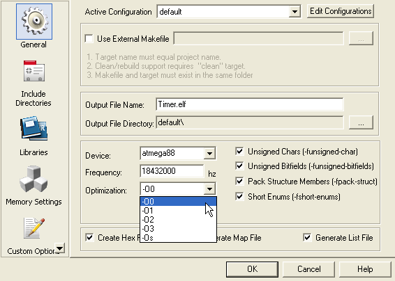
- Program doplňte podľa pokynov asistenta a odsimulujte.
Pozn.: Treba vypnúť optimalizáciu! (Project/Project options Pozri obr.) - Doplňte chýbajúce časti programu tak, aby LED blikala s frekvenciou 1 s.
- Vyskúšajte na svojej doske.
Prerušenia v AVR-GCC
PWM mode: When the PWM (PulseWidthModulation) mode is selected the Timer/Counter 1 can be used as an 8,9 or 10bit, free running PWM. Timer/Counter 1 acts as an up/down counter that is counting up from 0x0000 to the selected top (8bit -> 0x00FF, 9bit -> 0x01FF, 10bit -> 0x03FF), where it turns and counts down to 0x0000 and repeats this cycle endlessly. When the counter value matches the content of the compare register (OCR1A, OCR1B) it has an effect on the output pins OCA1 and OCB1 as follows: COM1X1 COM1X0 Effect on OCX1 0 0 no 0 1 no 1 0 cleared on compare match, up-counting, set on compare match, down-counting 1 1 cleared on compare match, down-counting, set on compare match, up-counting These bits are set in the register TCCR1A: (COM1A1 -> bit7, COM1A0 -> bit6, COM1B1 -> bit5, COM1B0 -> bit4) The right PWM mode is selected bits PWM10 (bit0 of TCCR1A) and PWM11 (bit1 of TCCR1A) as follows: PWM11 PWM10 Description 0 0 PWM mode disabled 0 1 8bit PWM 1 0 9bit PWM 1 1 10bit PWM Example: