Projekt: Snímač farby ColorPal
Zo stránky SensorWiki
Snímač farby ColorPAL
- Vypracovali:
- Bc. Tamás Vincze
- Bc. Adam Rozsár
- Študijný odbor: Aplikovaná mechatronika
- Ročník: 2.Ing
Zadanie
Zobrazte na LCD aktuálnu snímanú farbu zmeranú snímačom ColorPal.
Snímač a generátor farby ColorPAL
Vlastnosti
- Sníma celý rozsah farieb o ktorých dáva informáciu vo forme RGB (Red/Green/Blue) komponentov.
- Sníma spektrum okolitého osvetlenia s citlivosťou až 44uW/cm2 na lsb.
- Generuje 24 bitové farby pomocou vstavaného RGB LED.
- Možnosť pripojenia priamo na skúšobnú dosku alebo pomocou.
- Na detekciu a generovanie farby využíva sériovú komunikáciu cez jeden pin.
- Detekcia a generovanie farieb je riadené pomocou vstavaného mikrokontrolera.
- Disponuje vstavanou EEPROM pamäťou pre uloženie snímaných informácií a generačných programov.
- Autorun funkcia umožňuje spustenie vopred určeného programu iba použitím napájania.
Princíp činnosti
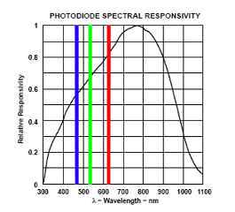
ColorPAL používa RGB LED na osvetlenie meranej farby (jedna farba naraz), spolu so široko spektrovým prevodníkom svetlo-napätie na meranie odrazeného svetla. Podľa množstva svetla ktoré sa odráža od meranej farby pri osvetlení od červenej, zelenej a modrej LED diódy je možné určiť farbu vzorky. ColorPAL používa sveteľný senzor TAOS typu TSL13T, ktorý má krivku spektrálnej citlivosťi nasledovný:
- Obr. 1: Krivka spektrálnej citlivosti prevodníka svetlo-napätie
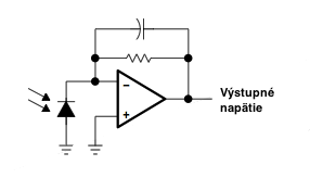
Prevodník je kombináciou fotodiódy a transimpedančného zosilňovača v jednom integrovanom obvode. Aktívna plocha fotodiódy je 0.5 mm x 0.5 mm a senzor vníma žiarenie s vlnovou dĺžkou v rozsahu od 320 nm do 1050 nm.Výstupné napätie sa mení lineárne s intenzitou dopadajúceho žiarenia.
- Obr. 2: Funkčná schéma zapojenie prevodníka
- Obr. 3: Pohľad z hora prevodníka
Výstupom snímača je napätie, úmerný všetkým svetlom ktoré detekuje a ktoré sú potom merané podľa hore uvedenek krivky spektrálnej citlivosti. Keď predmet je osvetlený iba červenou LED, tak snímač bude reagovať s napätím úmerným červenej zložky z farby predmetu a podobne s modrou a zelenou. Snímač a RGB LED diódy sú umiestnené vedľa seba v jednej plastickej trubice.
Použitie
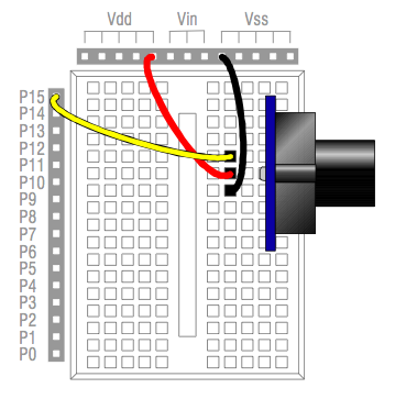
Senzor používa 3 piny: regulované +5V napájanie, zem a sériový dátový pin s otvoreným kolektorom. Pri práci sme snímač napojili na skúšobnú dosku podľa Obr. 2. Museli sme dávať pozor, aby bol jumper vhodne nastavený, na Vdd a nie na Vin.
- Obr. 4: Schéma zapojenia snímača ColorPAL
Programovanie
Komunikácia s ColorPAL-om je realizovaná cez seriálnu linku, prijímanie a odosielanie medzi 2400 a 7200 baudom. ColorPAL má v sebe zabudovaný pullup rezistor, preto nie je potrebné používať externe. Pretože používa open-drain protokol, pin ktorý sa používa na komunikáciu s ColorPAL-om by mal byť vždy nastavený ako vstupný, okrem prípadu keď ......... Pri inicializovania snímača musíme čakať aby ColorPAL dal tento pin do jednotky predtým než začneme posielať príkazy.
Snímač môže pracovať v rôznych módoch:
- Priamy mód: príkazy sú prijímané a vykonávané ihneď
- Bufferovací mód: príkazy sú prijímané a uložené do buffera pre použitie v budúcnosti
- Vykonávací mód: príkazy, ktoré sú uložené do EEPROM pamäte, sa vykonajú
Snímač vieme resetovať troma rôznymi spôsobmi:
- Powerup: pri prvom zapnutí ColorPAL začne vykonávať príkazy, ktoré sú uložené vo vnútornej pamäti EEPROM na adrese 00. Pri novom, ešte neprogramovanom snímači tento program prejde do priameho módu.
- Short Break: 7 milisekundová logická 0 resetuje snímač a začne sa vykonávať Powerup.
- Long Break: 80< milisekundová logická 0 resetuje snímač a vstúpy do Priameho módu.
Riešenie
Sériová linka používa piny D0 a D1 portu D mikropočítača. LCD panel,ktorý sme na paneli mali vopred zapojený používa tiež PORTD pre komunikáciu, kvôli čomu sme tento LCD modul nevedeli použiť na výpis výsledku merania snímača. Zapojili sme nový LCD modul, ktorý používa PORTB ako riadiacu zbernicu a PORTC ako dátovú zbernicu. Patričné zmeny sme vykonali aj v hlavičkových súboroch:
lcd.h
// DEM16216 LCD controller command set (do not modify these)
#include <avr/io.h>
#include <util/delay.h>


//#define LCD_DELAY		        asm volatile ("nop")
#define LCD_DELAY               _delay_us(5)
#define SETBIT(VAR,BIT)			(VAR|=(1<<BIT))
#define CLEARBIT(VAR,BIT)		(VAR&=~(1<<BIT))
#define CHECKBIT(VAR,BIT)		(VAR&(1<<BIT))

#define LCD_CLR             	0      // DB0: clear display
#define LCD_HOME            	1      // DB1: return to home position
#define LCD_ENTRY_MODE      	2      // DB2: set entry mode
#define LCD_ENTRY_INC       	1      //   DB1: increment
#define LCD_ENTRY_SHIFT     	0      //   DB2: shift
#define LCD_ON_CTRL         	3      // DB3: turn lcd/cursor on
#define LCD_ON_DISPLAY      	2      //   DB2: turn display on
#define LCD_ON_CURSOR       	1      //   DB1: turn cursor on
#define LCD_ON_BLINK        	0      //   DB0: blinking cursor
#define LCD_MOVE            	4      // DB4: move cursor/display
#define LCD_MOVE_DISP       	3      //   DB3: move display (0-> move cursor)
#define LCD_MOVE_RIGHT      	2      //   DB2: move right (0-> left)
#define LCD_FUNCTION        	5      // DB5: function set
#define LCD_FUNCTION_8BIT   	4      //   DB4: set 8BIT mode (0->4BIT mode)
#define LCD_FUNCTION_2LINES	3          //   DB3: two lines (0->one line)
#define LCD_FUNCTION_10DOTS 	2      //   DB2: 5x10 font (0->5x7 font)
#define LCD_CGRAM           	6      // DB6: set CG RAM address
#define LCD_DDRAM           	7      // DB7: set DD RAM address
// ________________________________________________________
#define LCD_BUSY            	7      // DB7: LCD is busy

// port and pins you will use for control lines
#define LCD_CTRL_PORT	PORTB
#define LCD_CTRL_DDR	DDRB
#define LCD_CTRL_RS		3
#define LCD_CTRL_RW		4
#define LCD_CTRL_E		5


// port you will use for data lines
#define LCD_DATA_PORT	PORTC
#define LCD_DATA_PIN	PINC
#define LCD_DATA_DDR	DDRC
#define LCD_DATA_D7		3
#define LCD_DATA_D6		2
#define LCD_DATA_D5		1
#define LCD_DATA_D4		0
// define pin which control backlight
#define LCD_CTRL_LIGHT	4

// access mode you will use (default is 8bit unless 4bit is selected)
		#define LCD_DATA_4BIT

// LCD display geometry
// change these definitions to adapt settings
#define LCD_LINES				2	// visible lines
#define LCD_LINE_LENGTH			16	// line length (in characters)
// cursor position to DDRAM mapping
#define LCD_LINE0_DDRAMADDR		0x00
#define LCD_LINE1_DDRAMADDR		0x40

// **************************************************

extern unsigned char lcdBusy(void);				// waits until LCD is not busy
extern void lcdControlWrite(unsigned char c_data);	// writes a control command to the LCD
extern unsigned char lcdControlRead(void);			// read the control status from the LCD
extern void lcdDataWrite(unsigned char w_data) ;	    // writes a data byte to the LCD screen at the current position
extern unsigned char lcdDataRead(void);				// reads the data byte on the LCD screen at the current position
extern void lcdInit4(void);

extern unsigned char ReadButtons();
extern void lcdStringWrite(char* String);
lcd.c
#include "lcd.h"


// **************************************************************************
// *************************** PUBLIC FUNCTIONS *****************************
// **************************************************************************

void lcdInit4(void)
{
    // Following two lines are a must when using BOOTLOADER:

    //UCSR0B = 0x00;                          // Disable RxD and TxD for UART0
                                            // Disable ALL interrupts (Global)
    SREG = SREG & 0x7F;                     // same as cli(); without Interrupts.h

                                            // initialize LCD control & data
										    // lines to output
   	PORTC = 0b00000000;						// pull-up on unused input
	DDRC  = 0b11111111;						// set ctrl & data as outputs
	PORTB = 0b00000000;						// pull-up on unused input
	DDRB  = 0b11111111;


	_delay_ms(50);        					// -  wait 15ms or more
											// -------------------
	CLEARBIT(PORTB, LCD_CTRL_RS);			// set RS to "control"
	CLEARBIT(PORTB, LCD_CTRL_RW);			// set R/W to "write"
											// 4 bit write
	SETBIT(PORTB, LCD_CTRL_E);			    // set "E" line
	PORTC = (PORTC | 0x03) & 0xF3;          // output data, high 4 bits
	LCD_DELAY;							    // wait
	CLEARBIT(PORTB, LCD_CTRL_E);			// clear "E" line
											// -------------------
	_delay_ms(5); 				            // -  wait 4.1ms
	SETBIT(PORTB, LCD_CTRL_E);	 	        // set "E" line
	LCD_DELAY;								// wait
	CLEARBIT(PORTB, LCD_CTRL_E);			// clear "E" line
											// -------------------
    _delay_ms(1);	                        // -  wait 0.1ms
	SETBIT(PORTB, LCD_CTRL_E);			    // set "E" line
	LCD_DELAY;						        // wait
	CLEARBIT(PORTB, LCD_CTRL_E);			// clear "E" line
											// -------------------
    _delay_ms(1);	                        // -  wait 0.1ms
    										// -------------------
	PORTC = (PORTC | 0x02) & 0xF2;	        // output data, high 4 bits
	SETBIT(PORTB, LCD_CTRL_E);		        // set "E" line
	LCD_DELAY;								// wait
	CLEARBIT(PORTB, LCD_CTRL_E);		    // clear "E" line
											// -------------------
	lcdControlWrite(0x28);					// 0x28	- function set (2 rows, 5x8 font)
     _delay_ms(50);
	lcdControlWrite(0x0C);					// 0x0C - display ON, cursor OFF
	lcdControlWrite(0x01);					// 0x01 - clear display
	lcdControlWrite(0x06); 					// 0x06 - shift right

}


// ************************************************************
// ********************** LOCAL FUNCTIONS *********************
// ************************************************************


void lcdControlWrite(unsigned char c_data)  // write the CONTROL byte to the display controller
{
	while(lcdBusy()) /* wait here */ ;		// wait until LCD not busy  or timeout

	CLEARBIT(PORTB, LCD_CTRL_RS);		    // set RS to "control"
	CLEARBIT(PORTB, LCD_CTRL_RW);	    	// set R/W to "write"

	PORTC = (PORTC&0xF0)|(c_data>>4);	    // output data, high 4 bits
	SETBIT(PORTB, LCD_CTRL_E);		        // set "E" line
	LCD_DELAY;								// wait
	CLEARBIT(PORTB, LCD_CTRL_E);	        // clear "E" line

	PORTC = (PORTC&0xF0) | (c_data&0x0F);	    // output data, low 4 bits
	SETBIT(PORTB, LCD_CTRL_E);		        // set "E" line
	LCD_DELAY;								// wait
	CLEARBIT(PORTB, LCD_CTRL_E);	        // clear "E" line
}


void lcdDataWrite(unsigned char w_data)     // write a DATA byte to the display
{
	while(lcdBusy())	 /* wait */ ;		// wait until LCD not busy or timeout

	SETBIT(PORTB, LCD_CTRL_RS);		        // set RS to "data"
	CLEARBIT(PORTB, LCD_CTRL_RW);		    // set R/W to "write"

	PORTC = (PORTC&0xF0)|(w_data>>4);	// output data, high 4 bits
	SETBIT(PORTB, LCD_CTRL_E);	            // set "E" line
	LCD_DELAY;								// wait
	CLEARBIT(PORTB, LCD_CTRL_E);		    // clear "E" line

	PORTC = (PORTC&0xF0) | (w_data&0x0F);	    // output data, low 4 bits
	SETBIT(PORTB, LCD_CTRL_E);		        // set "E" line
	LCD_DELAY;								// wait
	CLEARBIT(PORTB, LCD_CTRL_E);		    // clear "E" line
}

/* ------------------------------------------------------- */
/* Outputs string to a LCD (at current position)           */
/*                                                         */
/* ------------------------------------------------------- */

  void lcdStringWrite(char* String)
   {
     register uint8_t i=0;

	// check to make sure we have a good pointer
	if (!String) return;

	// print data
	while (String[i])
	{
		lcdDataWrite(String[i]);
		i++;
	}
}


/* ------------------------------------------------------- */
/*  Read and debounce the LCD AppMod buttons               */
/*                                                         */
/*  Returns 0 if nothing  is pressed                       */
/*  Returns 1 if button A is pressed                       */
/*  Returns 2 if button B is pressed                       */
/*  Returns 4 if button C is pressed                       */
/*  Returns 8 if button D is pressed                       */
/*  Returns combination if more is pressed (e.g. 6 for B+C)*/
/*                                                         */
/* ------------------------------------------------------- */

/*unsigned char ReadButtons()
{
  DDRD  = 0b00001110;                // make LCD bus inputs
  unsigned char state = 0xFF;           // assume nothing pressed

  for(int scan = 1; scan<=10; scan++)
  {
   state = state & ((PIND&0xF0)>>4); // make sure button held
   _delay_ms(5);                     // debounce 10 x 5 ms
  }

  DDRD  = 0b11111110;				 // return bus to outputs

  return(state);
}*/


/* ------------------------------------------------------- */
/* Test whether LCD is BUSY or READY for next command      */
/*                                                         */
/* At the moment it is replaced by the fixed time delay    */
/*                                                         */
/* Return values: 1 - OK                                   */
/*                0 - timeout                              */
/* ------------------------------------------------------- */

volatile unsigned char t_out_LCD;  // timeout displeja (krok 1024 us)
                                   // krok 1ms
unsigned char lcdBusy(void)
{
   _delay_ms(1);
   return 0;

/*
unsigned char pom;
	t_out_LCD=4; // pockam cca 4ms

	// wait until LCD busy bit goes to zero

	// do a read from control register

   CLEARBIT(LCD_CTRL_PORT, LCD_CTRL_RS);				// set RS to "control"

   LCD_DATA_PORT |=  0xF0;	// set pull-ups to on (4bit)
   LCD_DATA_DDR  &=  0x0F;	// set data I/O lines to input (4bit)

   SETBIT(LCD_CTRL_PORT, LCD_CTRL_RW);				// set R/W to "read"
   SETBIT(LCD_CTRL_PORT, LCD_CTRL_E);				// set "E" line
   LCD_DELAY;										// wait
   pom= LCD_DATA_PIN&0xF0;		// input data, high 4 bits
   CLEARBIT(LCD_CTRL_PORT, LCD_CTRL_E);		// clear "E" line
   LCD_DELAY;										// wait
   SETBIT(LCD_CTRL_PORT, LCD_CTRL_E);				// set "E" line
   LCD_DELAY;										// wait
   pom|=(LCD_DATA_PIN>>4)&0x0F;		// input data, low 4 bits
   CLEARBIT(LCD_CTRL_PORT, LCD_CTRL_E);		// clear "E" line

   while ((pom & (1<<LCD_BUSY))  && t_out_LCD )
   {
    SETBIT(LCD_CTRL_PORT, LCD_CTRL_E);				// set "E" line
    LCD_DELAY;										// wait
    pom=LCD_DATA_PIN&0xF0;		// input data, high 4 bits
    CLEARBIT(LCD_CTRL_PORT, LCD_CTRL_E);		// clear "E" line
    LCD_DELAY;										// wait
    SETBIT(LCD_CTRL_PORT, LCD_CTRL_E);				// set "E" line
    LCD_DELAY;										// wait
    pom|=(LCD_DATA_PIN>>4)&0x0F;		// input data, low 4 bits
    CLEARBIT(LCD_CTRL_PORT, LCD_CTRL_E);		// clear "E" line
   }

	//	leave data lines in input mode so they can be most easily used for other purposes
	if(t_out_LCD)
		return 1;	// ak vrati 1 timeout OK
	else
		return 0;		// ak vrati 0 timeout notOK
*/

}


/*
unsigned char lcdControlRead(void)
{
	// read the control byte from the display controller
	register unsigned char r_data=0;

	if(lcdBusyWait())	// wait until LCD not busy or time out
	{
		outb(LCD_DATA_PORT, inb(LCD_DATA_PORT)|0xF0);	// set pull-ups to on (4bit)
		outb(LCD_DATA_DDR, inb(LCD_DATA_DDR)&0x0F);	// set data I/O lines to input (4bit)
		CLEARBIT(LCD_CTRL_PORT, LCD_CTRL_RS);				// set RS to "control"
		SETBIT(LCD_CTRL_PORT, LCD_CTRL_RW);				// set R/W to "read"

		SETBIT(LCD_CTRL_PORT, LCD_CTRL_E);	// set "E" line
		LCD_DELAY;							// wait
		r_data = inb(LCD_DATA_PIN)&0xF0;		// input data, high 4 bits
		CLEARBIT(LCD_CTRL_PORT, LCD_CTRL_E);	// clear "E" line
		LCD_DELAY;							// wait
		SETBIT(LCD_CTRL_PORT, LCD_CTRL_E);	// set "E" line
		LCD_DELAY;							// wait
		r_data |= inb(LCD_DATA_PIN)>>4;		// input data, low 4 bits
		CLEARBIT(LCD_CTRL_PORT, LCD_CTRL_E);	// clear "E" line

		//	leave data lines in input mode so they can be most easily used for other purposes
	}
	return r_data;
}

unsigned char lcdDataRead(void)
{
// read a data byte from the display
	register unsigned char r_data =0;

	if(lcdBusyWait())				// wait until LCD not busy or time out
	{
		outb(LCD_DATA_PORT, inb(LCD_DATA_PORT)|0xF0);	// set pull-ups to on (4bit)
		outb(LCD_DATA_DDR, inb(LCD_DATA_DDR)&0x0F);	// set data I/O lines to input (4bit)
		SETBIT(LCD_CTRL_PORT, LCD_CTRL_RS);				// set RS to "data"
		SETBIT(LCD_CTRL_PORT, LCD_CTRL_RW);				// set R/W to "read"

		SETBIT(LCD_CTRL_PORT, LCD_CTRL_E);	// set "E" line
		LCD_DELAY;							// wait
		r_data = inb(LCD_DATA_PIN)&0xF0;		// input data, high 4 bits
		CLEARBIT(LCD_CTRL_PORT, LCD_CTRL_E);	// clear "E" line
		LCD_DELAY;							// wait
		SETBIT(LCD_CTRL_PORT, LCD_CTRL_E);	// set "E" line
		LCD_DELAY;							// wait
		r_data |= inb(LCD_DATA_PIN)>>4;		// input data, low 4 bits
		CLEARBIT(LCD_CTRL_PORT, LCD_CTRL_E);	// clear "E" line

	}
	//	leave data lines in input mode so they can be most easily used for other purposes
	return r_data;
}


*/
Potrebovali sme pripojiť k projektu ešte ďalšie súbory:serial.c serial.h
Zdrojový kód nášho programu:
#include "lcd.h"
#include "serial.h"
#include <stdio.h>

char sgetc(void)
{
while ((UCSR0A & (1 << RXC0)) == 0)                // Počká kým sú prijaté dáta
	  {
	    //  Nerobí nič, pokiaľ nie sú dáta prijaté a nie je pripravené čítať z UDR
	  };
      return UDR0;                               // prijatý bajt sa uloží do UDR0
}


int main(void)
{
char buffer[9];
inituart();

int i;

FILE mystdout = FDEV_SETUP_STREAM(sendchar, NULL, _FDEV_SETUP_WRITE); // "sendchar" je funkcia pre posielanie jedného znaku

inituart();                                                           //inicializácia sériovej linky
			_delay_ms(80);
unsigned char znak;
 			_delay_ms(2000);

     lcdInit4();                             // inicializacia v 4-bitovom rezime
     lcdControlWrite(1<<LCD_CLR);            // display clear
     lcdControlWrite(0x40);                  // pozicia 0,0

		lcdDataWrite(znak='A');
		lcdDataWrite(znak='H');      //testovanie výpisu na LCD panel
		lcdDataWrite(znak='O');
		lcdDataWrite(znak='J');


 	stdout = &mystdout;           // Odteraz funguje printf();

   	DDRD&=0xF8;		//0bemenet 1kimenet
	PORTD=0x00;		//PULL-UP beallitva

	DDRD|=0x06;
	PORTD=0x00;

		_delay_ms(80);

	DDRD&=0xFA;


