Acrob004: Rozdiel medzi revíziami
Zo stránky SensorWiki
Bez shrnutí editace |
Bez shrnutí editace |
||
| Riadok 14: | Riadok 14: | ||
Let's modify the circuit and try to measure the input with the microcontroller and display its value on the terminal. | Let's modify the circuit and try to measure the input with the microcontroller and display its value on the terminal. | ||
Modify the connection according the following diagram and download the attached piece of software. | Modify the connection according the following diagram and download the attached piece of software. | ||
[[Obrázok:AcrobPushbutton02.jpg]] | |||
<source lang="c"> | <source lang="c"> | ||
| Riadok 37: | Riadok 39: | ||
Another example uses the switch to control the LED. Exactly as in the first experiment, but now the controller makes the | Another example uses the switch to control the LED. Exactly as in the first experiment, but now the controller makes the | ||
decision. | decision. | ||
[[Obrázok:AcrobPushbutton03.jpg]] | |||
<source lang="c"> | <source lang="c"> | ||
Verzia z 14:20, 12. jún 2010
< Previous | Home | Next >
Pushbutton
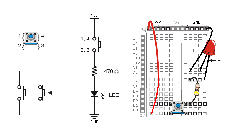
To test the pushbutton, please connect one LED with current limiting resistor together with a pushbutton:
This setup doesn't require microcontroller, it is just to test it and recognize its function, pinout and operation. No program required!
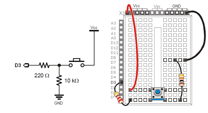
Let's modify the circuit and try to measure the input with the microcontroller and display its value on the terminal. Modify the connection according the following diagram and download the attached piece of software.
#define SWITCH 3                 // select the pin for Switch

void setup()
{
 Serial.begin(9600);
 pinMode(SWITCH, INPUT );        // this pin is an INPUT
 Serial.println("Button test:");
}

void loop()                      // endless loop
{
 Serial.print("Input D3 = ");
 Serial.println(digitalRead(SWITCH),BIN);
 delay(250);                     // wait 1/4s for another
}
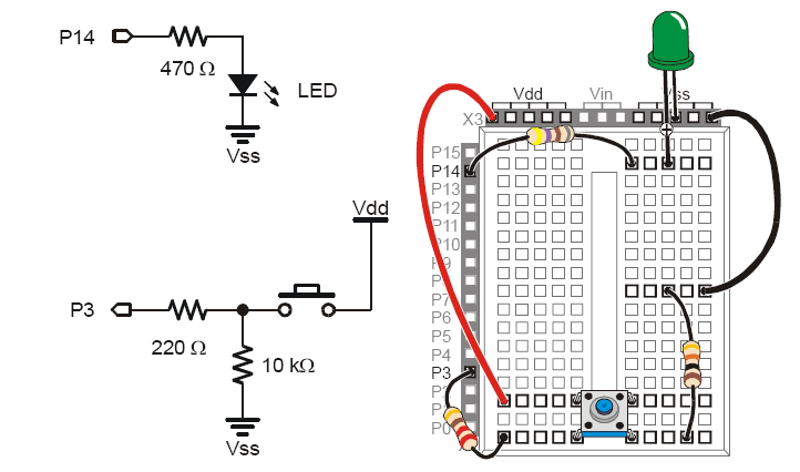
Another example uses the switch to control the LED. Exactly as in the first experiment, but now the controller makes the
decision.
/*
  Button

 Turns on and off a light emitting diode(LED) connected to digital
 pin 13, when pressing a pushbutton attached to pin 7.


 The circuit:
 * LED attached from pin 13 to ground
 * pushbutton attached to pin 2 from +5V
 * 10K resistor attached to pin 2 from ground

 * Note: on most Arduinos there is already an LED on the board
 attached to pin 13.


 created 2005
 by DojoDave <http://www.0j0.org>
 modified 17 Jun 2009
 by Tom Igoe

  http://www.arduino.cc/en/Tutorial/Button
 */

// constants won't change. They're used here to
// set pin numbers:
const int buttonPin = 2;     // the number of the pushbutton pin
const int ledPin =  13;      // the number of the LED pin

// variables will change:
int buttonState = 0;         // variable for reading the pushbutton status

void setup() {
  // initialize the LED pin as an output:
  pinMode(ledPin, OUTPUT);
  // initialize the pushbutton pin as an input:
  pinMode(buttonPin, INPUT);
}

void loop(){
  // read the state of the pushbutton value:
  buttonState = digitalRead(buttonPin);

  // check if the pushbutton is pressed.
  // if it is, the buttonState is HIGH:
  if (buttonState == HIGH) {
    // turn LED on:
    digitalWrite(ledPin, HIGH);
  }
  else {
    // turn LED off:
    digitalWrite(ledPin, LOW);
  }
}
< Previous | Home | Next >


