Acrob008: Rozdiel medzi revíziami
Zo stránky SensorWiki
Nová stránka: = Úloha 5 = == Line Sensor == center Ako jednoduchý senzor čiary použijeme QTI Line Sensor firmy Parallax. Skladá sa z infračervenej LED ... |
Bez shrnutí editace |
||
| (2 medziľahlé úpravy od rovnakého používateľa nie sú zobrazené.) | |||
| Riadok 1: | Riadok 1: | ||
[[Acrob007|< Previous]] | [[Acrob|Home]] | [[Acrob009|Next >]] | |||
== Line Sensor == | == Line Sensor == | ||
| Riadok 6: | Riadok 6: | ||
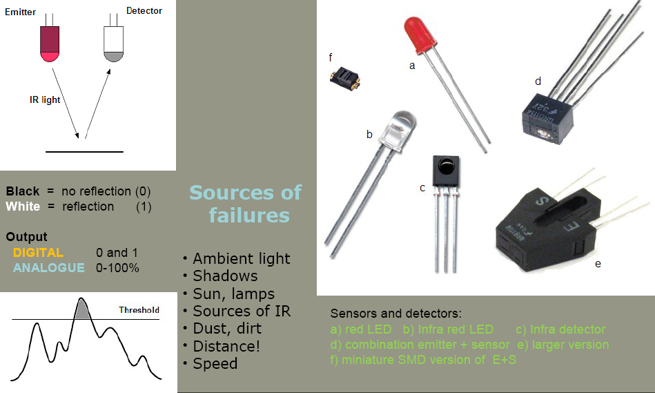
[[Obrázok:IRsensorPrinciple.png|center]] | [[Obrázok:IRsensorPrinciple.png|center]] | ||
As a simple line sensor is used the QTI Line Sensor by Parallax. It consists of infrared LED and phototransistor. Phototransistor is opening depending on amount of reflected IR light. | |||
LED is switched ON when White line is Vcc and Black on GND. Third pin is a phototransistor output. | |||
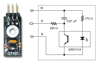
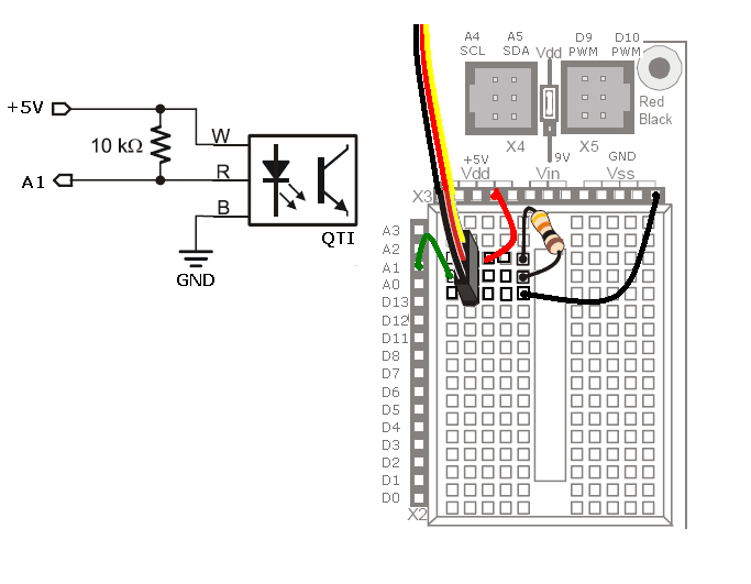
To measure reasonable value, it is necessary to connect also a pull-up resistor according the figure. | |||
* [http://www.parallax.com/dl/docs/prod/compshop/qtilinesensorrev1.pdf | * [http://www.parallax.com/dl/docs/prod/compshop/qtilinesensorrev1.pdf QTI Sensor Datasheet] | ||
[[Obrázok:QTIsensorDiagram.png|center]] | [[Obrázok:QTIsensorDiagram.png|center]] | ||
Following program measure output voltage of the sensor connected to the analogue input 1. | |||
<source lang="c"> | <source lang="c"> | ||
| Riadok 49: | Riadok 50: | ||
[[Obrázok:QTILineSensorConnection.png|center]] | [[Obrázok:QTILineSensorConnection.png|center]] | ||
<!-- | |||
Niekedy môže byť výhodné zapojiť aj napájanie IR LED diódy na niektorý pin procesora. Môžeme tak IR LED vypnúť vtedy, keď nemeria. | Niekedy môže byť výhodné zapojiť aj napájanie IR LED diódy na niektorý pin procesora. Môžeme tak IR LED vypnúť vtedy, keď nemeria. | ||
To okrem úspory energie významne zníži vzájomné ovplvyvňovanie viacerých senzorov medzi sebou. | To okrem úspory energie významne zníži vzájomné ovplvyvňovanie viacerých senzorov medzi sebou. | ||
--> | |||
As an inspiration, look for a mounting instruction, connection and program for line following of | |||
the producer - [http://www.parallax.com/dl/docs/prod/robo/QTILineFollow.pdf QTI Line Following Sensor]. | |||
[[ | [[Acrob007|< Previous]] | [[Acrob|Home]] | [[Acrob009|Next >]] | ||
Aktuálna revízia z 09:55, 23. jún 2010
< Previous | Home | Next >
Line Sensor

As a simple line sensor is used the QTI Line Sensor by Parallax. It consists of infrared LED and phototransistor. Phototransistor is opening depending on amount of reflected IR light. LED is switched ON when White line is Vcc and Black on GND. Third pin is a phototransistor output. To measure reasonable value, it is necessary to connect also a pull-up resistor according the figure.

Following program measure output voltage of the sensor connected to the analogue input 1.
#define LED_Yellow  13   // select the pin for the green LED
#define SENSOR_1     1

int pos = 0;            // variable to store the servo position
long val = 0;           // variable to store the value coming from the sensor
long Threshold = 0;           // variable to store the value coming from the sensor
byte SensorState = B0000;

void setup()
{
  pinMode(LED_Yellow, OUTPUT);    // declare this pin as an OUTPUT

  Serial.begin(9600);

  Serial.println("Test started   \n");
  delay(1000);
}


void loop()
{
    val = analogRead(SENSOR_1);     // read the value from the sensor

  Serial.print("Sensor = ");
  Serial.println(val, DEC);
  delay(200);

}   /* End of Loop */

As an inspiration, look for a mounting instruction, connection and program for line following of
the producer - QTI Line Following Sensor.
< Previous | Home | Next >