Acrob003: Rozdiel medzi revíziami
Zo stránky SensorWiki
| Riadok 27: | Riadok 27: | ||
It is necessary to determine whether the certain pin will be configured as an INPUT or OUTPUT one. This is done in Setup section using the command <TT> | It is necessary to determine whether the certain pin will be configured as an INPUT or OUTPUT one. This is done in Setup section using the command <TT> | ||
pinMode( PIN_NUMBER, IPUT/OUTPUT );</TT>. To avoid annoying searching through the code in the case we move the LED from certain pin to another, | |||
instead of "hardcoded" pinnumber for LED we use a substitution <TT>#define LED_Yellow 13</TT>. In case of modification, it is necessary to change | |||
the configuration only on this one line. | |||
Then, after an initialization the programm enters the main loop. Command <TT>digitalWrite(LED_Yellow, HIGH/LOW); </TT> can change the state of the | |||
output HIGH (i.e. logical One, electrical +5V) or LOW (i.e. logical Zero, electrical 0V). Certainly, the electrical voltage present on the output | |||
pin makes LED lit, and vice versa. The pin remains in its output state until it is again changed. So the LED remains on for the certain amount of the time which is defined by the <TT>delay(Period); </TT> command, where ''Period'' is defined in miliseconds (1/1000 s). | |||
=== Your turn === | === Your turn === | ||
Verzia z 09:06, 12. jún 2010
LED blink

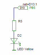
Your board contains one user programmable LED diode (see schematic). Let's try to controll it using the followng programm:
#define LED_Yellow 13                // select the pin for LED

void setup()
{
 pinMode(LED_Yellow, OUTPUT );       // this pin is an OUTPUT
}

void loop() // endless loop
{
 digitalWrite(LED_Yellow, HIGH);    // make it visible
 delay(1000);                       // wait 1000 ms = 1s
 digitalWrite(LED_Yellow, LOW);     // turn off
 delay(1000);                       // wait again
}
How it works
It is necessary to determine whether the certain pin will be configured as an INPUT or OUTPUT one. This is done in Setup section using the command
pinMode( PIN_NUMBER, IPUT/OUTPUT );. To avoid annoying searching through the code in the case we move the LED from certain pin to another,
instead of "hardcoded" pinnumber for LED we use a substitution #define LED_Yellow 13. In case of modification, it is necessary to change the configuration only on this one line.
Then, after an initialization the programm enters the main loop. Command digitalWrite(LED_Yellow, HIGH/LOW); can change the state of the output HIGH (i.e. logical One, electrical +5V) or LOW (i.e. logical Zero, electrical 0V). Certainly, the electrical voltage present on the output pin makes LED lit, and vice versa. The pin remains in its output state until it is again changed. So the LED remains on for the certain amount of the time which is defined by the delay(Period); command, where Period is defined in miliseconds (1/1000 s).
Your turn
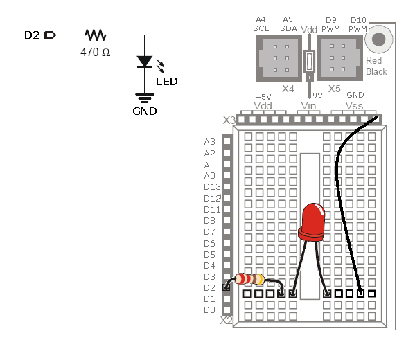
Connect Your own LED on the experimental breadboard. Connect the LED to the pin D2, it will be assigned with number 2 in Your program digitalWrite(2,HIGH).

Change the program to blink with both LEDs - Your and the onboard. Can You program them tu blink mutually like on the railway crosses?
< Previous | Home | Next >