Acrob008
Zo stránky SensorWiki
< Previous | Home | Next >
Line Sensor

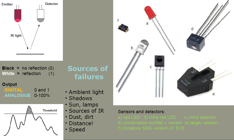
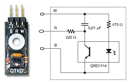
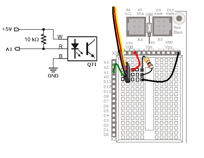
As a simple line sensor is used the QTI Line Sensor by Parallax. It consists of infrared LED and phototransistor. Phototransistor is opening depending on amount of reflected IR light. LED is switched ON when White line is Vcc and Black on GND. Third pin is a phototransistor output. To measure reasonable value, it is necessary to connect also a pull-up resistor according the figure.

Following program measure output voltage of the sensor connected to the analogue input 1.
#define LED_Yellow  13   // select the pin for the green LED
#define SENSOR_1     1

int pos = 0;            // variable to store the servo position
long val = 0;           // variable to store the value coming from the sensor
long Threshold = 0;           // variable to store the value coming from the sensor
byte SensorState = B0000;

void setup()
{
  pinMode(LED_Yellow, OUTPUT);    // declare this pin as an OUTPUT

  Serial.begin(9600);

  Serial.println("Test started   \n");
  delay(1000);
}


void loop()
{
    val = analogRead(SENSOR_1);     // read the value from the sensor

  Serial.print("Sensor = ");
  Serial.println(val, DEC);
  delay(200);

}   /* End of Loop */

As an inspiration, look for a mounting instruction, connection and program for line following of
the producer - QTI Line Following Sensor.
< Previous | Home | Next >