LCD displej s radičom HD44780: Rozdiel medzi revíziami
Z SensorWiki
(→Opis displeja) |
|||
| Riadok 3: | Riadok 3: | ||
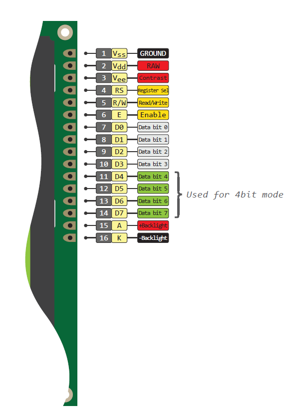
| − | [[Súbor:HD44780pinout.png|200]] | + | [[Súbor:HD44780pinout.png|200|left]] |
| + | #Ground | ||
| + | #VCC +3.3 to +5V (typical) | ||
| + | #Contrast adjustment (VO) This is an analog input, typically connected to a potentiometer. The user must be able to control this voltage independent of all other adjustments, in order to optimise visibility of the display that varies i.a. with temperature, and, in some cases height above the sea level. With a wrong adjustment the display will seem to malfunction. | ||
| + | #Register Select (RS). RS=0: Command, RS=1: Data | ||
| + | #Read/Write (R/W). R/W=0: Write, R/W=1: Read (In most applications reading from the HD44780 makes no sense. In that case this pin can be permanently connected to ground and no io pins need to be allocated to steer it.) | ||
| + | #Clock (Enable). Falling edge triggered | ||
| + | #Bit 0 (Not used in 4-bit operation) | ||
| + | #Bit 1 (Not used in 4-bit operation) | ||
| + | #Bit 2 (Not used in 4-bit operation) | ||
| + | #Bit 3 (Not used in 4-bit operation) | ||
| + | #Bit 4 | ||
| + | #Bit 5 | ||
| + | #Bit 6 | ||
| + | #Bit 7 | ||
| + | #Backlight Anode (+) (If applicable) | ||
| + | #Backlight Cathode (-) (If applicable) | ||
== Pripojenie == | == Pripojenie == | ||
Verzia zo dňa a času 23:14, 29. január 2021
Opis displeja
- Ground
- VCC +3.3 to +5V (typical)
- Contrast adjustment (VO) This is an analog input, typically connected to a potentiometer. The user must be able to control this voltage independent of all other adjustments, in order to optimise visibility of the display that varies i.a. with temperature, and, in some cases height above the sea level. With a wrong adjustment the display will seem to malfunction.
- Register Select (RS). RS=0: Command, RS=1: Data
- Read/Write (R/W). R/W=0: Write, R/W=1: Read (In most applications reading from the HD44780 makes no sense. In that case this pin can be permanently connected to ground and no io pins need to be allocated to steer it.)
- Clock (Enable). Falling edge triggered
- Bit 0 (Not used in 4-bit operation)
- Bit 1 (Not used in 4-bit operation)
- Bit 2 (Not used in 4-bit operation)
- Bit 3 (Not used in 4-bit operation)
- Bit 4
- Bit 5
- Bit 6
- Bit 7
- Backlight Anode (+) (If applicable)
- Backlight Cathode (-) (If applicable)
Pripojenie
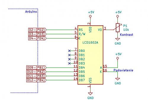
Schéma zapojenia
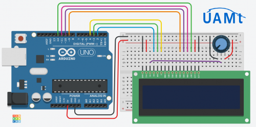
Pokúste sa najprv pripojiť displej len podľa schémy zapojenia. Ak sa vám to nepodarí, alebo si chcete byť naistom, skontrolujte si zapojenie aj podľa zapojovacej schémy.
To, či máte displej pripojený správne si môžete vyskúšať týmto demo programom, ktorý preložíte a nahráte z prostredia Arduino.
#include <LiquidCrystal.h>
// connection      RS R/W E D4 D5 D6 D7
LiquidCrystal lcd ( 2,  3,4, 9,10,11,12);

// define some user characters
byte smiley[8] = {
  0b00000,
  0b00000,
  0b01010,
  0b00000,
  0b00000,
  0b10001,
  0b01110,
  0b00000 };

byte step1[8] = {
  0b01100, 0b01100, 0b00000, 0b01110,
  0b11100, 0b01100, 0b11010, 0b10011};

byte step2[8] = {
  0b01100, 0b01100, 0b00000, 0b01100,
  0b01100, 0b01100, 0b1100,  0b01110};

void setup() {
  lcd.begin(16, 2);    // init LCD + set number of columns and rows

  lcd.createChar(1, smiley);    // create a new characters
  lcd.createChar(3, step1);
  lcd.createChar(4, step2);

  lcd.setCursor(0, 0);          // set the cursor to the top left

  lcd.write(byte(1));           // smiley
  lcd.print(" UAMT FEI STU ");  // normal text
  lcd.write((byte)1);           // smiley
}

void loop() {
    lcd.setCursor(2, 1);         // set curspr to line 2 col 3
    lcd.print("time: ");         // print the number of seconds since reset:
    lcd.print(millis() / 1000);
    lcd.setCursor(12, 1);
    lcd.write(3);                // draw the little man
    delay(delayTime);
    lcd.setCursor(12, 1);
    lcd.write(4);
    delay(delayTime);
}
ToDo
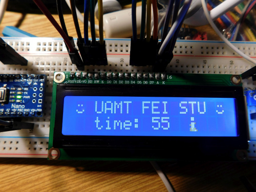
Na displeji by sa vám mal zobraziť text, počítadlo a jednoduchá animácia ako na obrázku
Q: Čo s nepoužitými vstupmi?
A1: pripojiť na definovanú úroveň, najlepšie cez pull-up/pull-down rezistor.
A2: Keďže podľa datasheetu[REF 1] má riadiaci obvod Hitachi HD44780 zapojené pull-upy interne, tak nie sú potrebné.
A3: Keďže však nevieme, aký riadiaci čip je v skutočnosti použitý, pre istotu ich môžeme zapojiť.
Vysvetlivky, prečo sú nezapojené vstupy nebezpečné:
Nezapojené (plávajúce) vstupy sú oveľa citlivejšie na ESD (elektrostatický výboj) a taktiež zvyšujú zbytočne spotrebu obvodu. Odporúča sa pripojenie cez tzv. pull-up odpor priamo na zem, prípadne aj bez odporu. Druhá možnosť, pripojenie na kladné napájacie napätie je tiež možná, ale v tomto prípade sa vynechanie pull-up rezistora neodporúča.
Toto je jeden z príkladov mnohých takýchto odporúčaní[REF 2] priamo od firmy NxP:
|
5.3 Line Termination and Pullup/Pulldown Resistors
|
Literatúra
- ↑ Hitachi HD44780U Dot Matrix Liquid Crystal Display Controller/Driver. ADE-207-272(Z), Japan, 1999.
- ↑ Murray Stewart: AN3393: MC9RS08KA Application Hints. NxP/Freescale Semiconductor Application Note, 2007.
Odkazy
- Datasheets
- Basic LCD Datasheet (PDF)
- HD44780 (PDF)
- Wikipedia o HD44780 https://en.wikipedia.org/wiki/Hitachi_HD44780_LCD_controller
- Generátor vlastných znakov
- Arduino Reference Library: LiquidCrystal
- Kniznice lcd.c a lcd.h od P. Fleuryho https://github.com/damadmai/pfleury
- Tinkercad model s LCD displejom a demo programom https://www.tinkercad.com/things/iO56bA1E68T-copy-of-lcd/editel?sharecode=vmfhh-3g1G2NVAtB_BFJZQtqwN3hdpEsSGQGGtChMDc


