555
Zo stránky SensorWiki
Astabilný oscilátor s NE 555
Jednoduchý modul s oscilátorom a prepínateľnou výstupnou frekvenciou. Jeho základom je jeden z najstarších, avšak dodnes vyrábaných, integrovaných obvodov NE 555. Okrem dvoch pinov, ktoré sú použité na napájanie (+5V, GND) má jeden výstup (Output) na ktorom odoberáme výstupný signál.
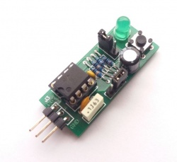
- Napájanie: +5V
- Výstup: TTL kompatibilný, 5V, oscilátor alebo manuálne tlačidlom
- Frekvencie: 1 kHz, 50 Hz, 1 Hz, voliteľné prepojkou
- Oscilátor: NE 555 (datasheet)
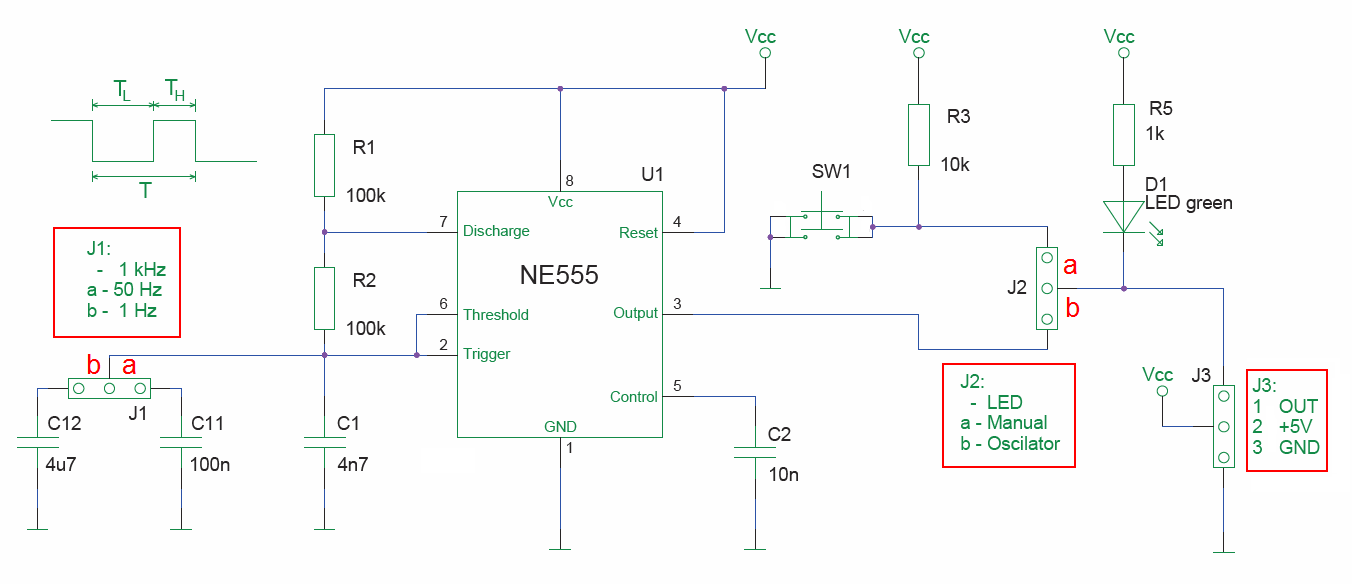
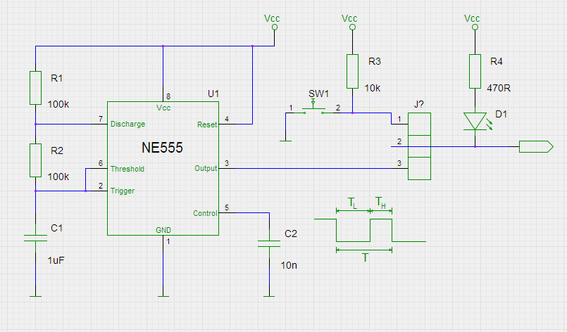
Schéma zapojenia modulu.
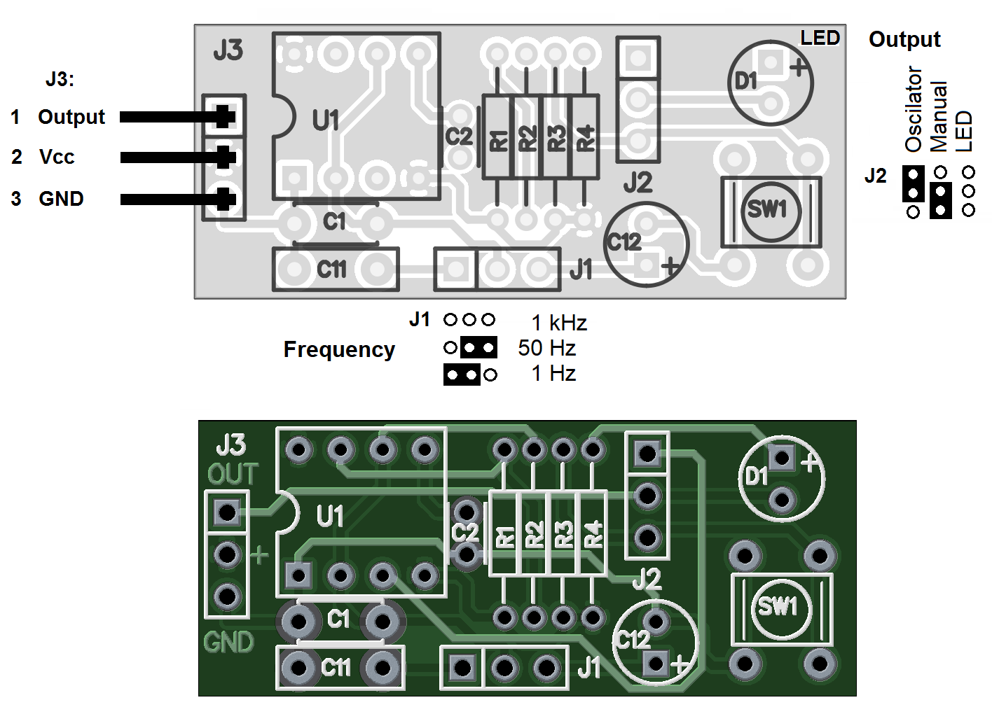
Nastavenie konfiguračných prepojok.
Na základe informácie z datasheetu je vzťah pre výpočet periódy T výstupného signálu
kde C1 je kapacita kondenzátora Farads, R1 & R2 are in Ohms, so for values in schematic:
T = 0,693 × ( 100 000 + 2 × 100 000) × 0.000001 = 0,2 seconds (or 4,8 Hz)
If you want a different frequency, you have to change the values of C1, R1 & R2. As an example - if change from a 1 µF capacitor to 10 µF, it will take 10x the time to charge, so your frequency will go down by a factor of 10.
Popis funkcie integrovaného obvodu NE 555 nájdete na rozličných miestach, napríklad aj na Wikipedii. Funkcia obvodu je pekne viditeľná v simulátore. Okrem oscilátora je možné s obvodom zostaviť aj veľké množstvo ďalších obvodov - monostabilný multivibrátor, komparátor, okienkový komparátor atď.
Astable (oscilating) circuit
The oscilating circuit diagram is pretty simple, featuring the 555, and then a couple of resistors & capacitors that define the actual frequency of the oscillation. Pay attention to the pin numbers.
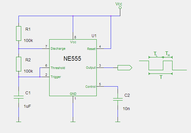
In reality, when you build it out, the circuit should look like this one:
TODO: image
You can calculate frequency using this formula:
T = 0,693 × (R1 + 2×R2) × C1
C1 is measured in Farads, R1 & R2 are in Ohms, so for values in schematic:
T = 0,693 × ( 100 000 + 2 × 100 000) × 0.000001 = 0,2 seconds (or 4,8 Hz)
If you want a different frequency, you have to change the values of C1, R1 & R2. As an example - if change from a 1 µF capacitor to 10 µF, it will take 10x the time to charge, so your frequency will go down by a factor of 10.
Measuring the frequency
volatile long lasttime = 0; // volatile is necessary, since this value is changed in an interrupt

void setup()
{
  Serial.begin(9600);
  Serial.println("Measured time [ms]:");

  pinMode(3, INPUT);                    // make pin D3 (PD.3=INT1) input
  attachInterrupt( 1, onTick, RISING);  // set interrupt 1 (from pin 3) to call 'onTick'
                                        // when the signal rises.
}


void loop()
{
  /* Nothing to do here, everything happens in interrupt service routine onTick */
}


void onTick()   // print out how many milliseconds occurred between the last
                // clock tick and this one.
{
  long thistime=millis();
  char tmp[7];
  sprintf(tmp, "%6d", thistime-lasttime);
  Serial.print(tmp);
  Serial.print("\r");
//    Serial.println(thistime-lasttime);
   lasttime = thistime;
}
More components to add and use for MMP exercises:


![{\displaystyle \left[F\right]\times 3}](https://wikimedia.org/api/rest_v1/media/math/render/svg/03b9bb9c50579604ab51e3f3a33700352d1216ec)