555
Z SensorWiki
Astable (oscilating) circuit
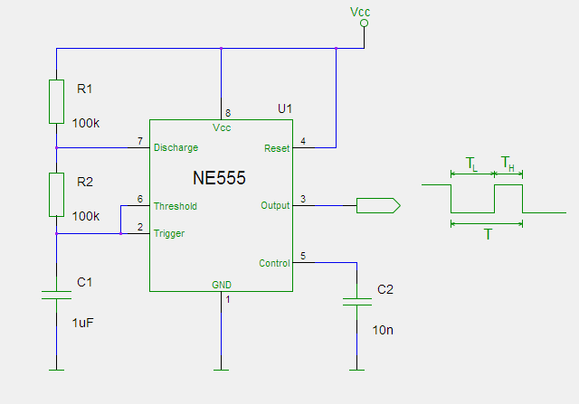
The oscilating circuit diagram is pretty simple, featuring the 555, and then a couple of resistors & capacitors that define the actual frequency of the oscillation. Pay attention to the pin numbers.
In reality, when you build it out, the circuit should look like this one:
TODO: image
You can calculate frequency using this formula:
T = 0,693 × (R1 + 2×R2) × C1
C1 is measured in Farads, R1 & R2 are in Ohms, so for values in schematic:
T = 0,693 × ( 100 000 + 2 × 100 000) × 0.000001 = 0,2 seconds (or 4,8 Hz)
If you want a different frequency, you would change the values of C1, R1 & R2. Changing the capicitor is the easiest to imagine -- if you go from a 10 µF capacitor to 1 µF, it will take 1/10 the time to charge, so your frequency will go up by a factor of 10.
Measuring the frequency with Arduino
// since this value is changed in an interrupt handler,
// mark it as volatile.
volatile long lasttime = 0;

void setup()
{
  // Go with faster than normal serial speed
  Serial.begin(115200);

  // Set Interrupt 0 (which is on digital pin 2) to call 'onTick'
  // when the signal rises.
  pinMode(2, INPUT);
  attachInterrupt( 0, onTick, RISING );
}


void loop()
{
  // Note that we're doing anything in the main loop,
  // everything happens in onTick
}


void onTick()
{
  // print out how many milliseconds occurred between the last
  // clock tick and this one.
  long thistime=millis();
  Serial.println(thistime-lasttime);
  lasttime = thistime;
}
