555
Zo stránky SensorWiki
Časovač 555
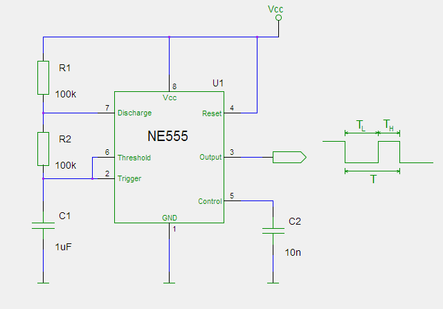
The oscilating circuit diagram is pretty simple, featuring the 555, and then a couple of resistors & capacitors that define the actual frequency of the oscillation. Pay attention to the pin numbers.

In reality, when you build it out, the circuit should look like this one:
TODO: image
You can calculate frequency using this formula:
T = 0,693 × (R1 + 2×R2) × C1
C1 is measured in Farads, R1 & R2 are in Ohms, so for values in schematic:
T = 0,693 × ( 100 000 + 2 × 100 000) × 0.00001 = 0.99792 seconds (or 1.002 Hz)
If you want a different frequency, you would change the values of C1, R1 & R2. Changing the capicitor is the easiest to imagine -- if you go from a 10 µF capacitor to 1 µF, it will take 1/10 the time to charge, so your frequency will go up by a factor of 10.