Segmentový display TM1637
Zo stránky SensorWiki
Záverečný projekt predmetu MIPS / LS2023 - Juraj Štefánik
Zadanie
Segmentový display TM1637 - napíšte rutiny na zobrazenie čísla a času na tomto displeji. Predvedenie funkcie si vymyslite, napr. stopky a pod.
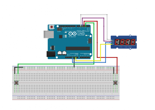
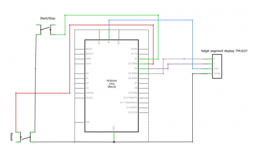
Predvedenie funkcie je realizované pomocou programu pre stopky,ktoré sú ovládané dvomi tlačidlami. Prvé tlačidlo Slúži pre Štart/Stop a druhé pre Reset.


Literatúra:
Analýza a opis riešenia
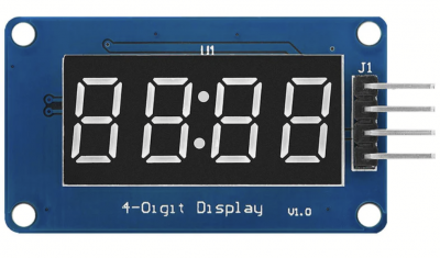
TM1637 TM1637 je obvod ovládajúci 7-segmentový displej. Tento obvod umožňuje jednoduchú komunikáciu s displejom a riadenie zobrazených číslic a segmentov.
Komunikácia s TM1637 prebieha pomocou jednoduchého sériového rozhrania, ktoré využíva dva piny - CLK (Clock) a DIO (Data Input/Output). CLK riadi synchronizáciu dátových prenosov a DIO slúži na prenos dát.
Princím funkcie Pri spustení programu sa na displeji objavia 4 nuly a dvojbodka v strede. Po zatlačení tlačidla Start/Stop sa stopky spustia.Na displeji beží čas až pokým sa opäť nestlačí tlačidlo Start/Stop.Vtedy sa stopky zastavia a na displeji svieti čas, v ktorom boli stopky zastavené. Po opätovnom stlačení tlačidla čas začne bežať od mista kde bol zastavený. Tlačidlo Reset slúži na nastavenie začiatku (stav 00:00 na displeji),nezaisťuje však to, aby sa stopky zastavili.


Algoritmus a program
Algoritmus programu je....
#include <avr/io.h>

#define F_CPU 16000000UL  //define CPU frequency

//Required libraries
#include <stdio.h>
#include <avr/io.h>
#include <util/delay.h>
#include <avr/interrupt.h>

#define set_bit(ADDRESS,BIT) (ADDRESS |= (1<<BIT))
#define clear_bit(ADDRESS,BIT) (ADDRESS &= ~(1<<BIT))

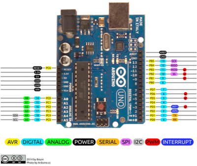
#define CLK  PD5  // CLK -> pin 5 portD.5
#define DIO  PD4  // DIO -> pin 4 portD.4

#define START_STOP_PIN PD2 // START_STOP_PIN -> pin 2 portD.2
#define RESET_PIN PD3 // RESET_PIN -> pin 3 portD.3


#define BIT_DELAY 100  //delay 100ms

//define for TM1637
#define TM1637_I2C_COMM1    0x40
#define TM1637_I2C_COMM2    0xC0
#define TM1637_I2C_COMM3    0x80


//
//      A
//     ---
//  F |   | B
//     -G-
//  E |   | C
//     ---
//      D
const uint8_t digitToSegment[] = {
	// XGFEDCBA
	0b00111111,    // 0
	0b00000110,    // 1
	0b01011011,    // 2
	0b01001111,    // 3
	0b01100110,    // 4
	0b01101101,    // 5
	0b01111101,    // 6
	0b00000111,    // 7
	0b01111111,    // 8
	0b01101111,    // 9
	0b01110111,    // A
	0b01111100,    // b
	0b00111001,    // C
	0b01011110,    // d
	0b01111001,    // E
	0b01110001     // F
};

static const uint8_t minusSegments = 0b01000000;

uint8_t brightness = (0x7 & 0x7) | 0x08;

void displayInit(){
	clear_bit(DDRD,CLK);  // set CLK as input
	set_bit(PORTD,CLK);  // CLK as input pull-up on

	clear_bit(DDRD,DIO);  // set DIO as input
	set_bit(PORTD,DIO);  // DIO as input pull-up on
}

void startCom(){
	set_bit(DDRD,DIO);  // set DIO as output
	clear_bit(PORTD,DIO);  // set DIO as output
	_delay_us(BIT_DELAY);
}

void stopCom(){
	set_bit(DDRD,DIO);  // set DIO as output
	clear_bit(PORTD,DIO);  // set DIO as output
	_delay_us(BIT_DELAY);

	clear_bit(DDRD,CLK);  // set CLK as input
	set_bit(PORTD,CLK);  // CLK as input pull-up on
	_delay_us(BIT_DELAY);

	clear_bit(DDRD,DIO);  // set DIO as input
	set_bit(PORTD,DIO);  // DIO as input pull-up on
	_delay_us(BIT_DELAY);
}

int displayWriteByte(uint8_t byte){
	uint8_t data = byte;

	// 8 Data Bits
	for(uint8_t i = 0; i < 8; i++) {
		// CLK low
		set_bit(DDRD,CLK);
		clear_bit(PORTD,CLK);
		_delay_us(BIT_DELAY);

		// Set data bit
		if (data & 0x01){
			clear_bit(DDRD,DIO);  // set DIO as input
			set_bit(PORTD,DIO);  // DIO as input pull-up on
		} else{
			set_bit(DDRD,DIO);  // set DIO as output
			clear_bit(PORTD,DIO);
		}


		_delay_us(BIT_DELAY);

		// CLK high
		clear_bit(DDRD,CLK);  // set CLK as input
		set_bit(PORTD,CLK);  // CLK as input pull-up on
		_delay_us(BIT_DELAY);
		data = data >> 1;
	}

	// Wait for acknowledge
	// CLK to zero
	set_bit(DDRD,CLK);  // set CLK as output
	clear_bit(PORTD,CLK);

	clear_bit(DDRD,DIO);  // set DIO as input
	set_bit(PORTD,DIO);  // DIO as input pull-up on
	_delay_us(BIT_DELAY);

	// CLK to high
	clear_bit(DDRD,CLK);  // set CLK as input
	set_bit(PORTD,CLK);  // CLK as input pull-up on
	_delay_us(BIT_DELAY);
	uint8_t ack = !bit_is_clear(PIND, DIO);
	if (ack == 0)
	set_bit(DDRD,DIO);  // set DIO as output
	clear_bit(PORTD,DIO);


	_delay_us(BIT_DELAY);
	set_bit(DDRD,CLK);  // set CLK as output
	clear_bit(PORTD,CLK);
	_delay_us(BIT_DELAY);

	return ack;
}

void displayShowDots(uint8_t dots, uint8_t* digits){
	for(int i = 0; i < 4; ++i)
	{
		digits[i] |= (dots & 0x80);
		dots <<= 1;
	}

}

uint8_t displayEncodeDigit(uint8_t digit){
	return digitToSegment[digit & 0x0f];
}

void displaySetSegments(const uint8_t segments[], uint8_t length, uint8_t pos){
	// Write COMM1
	startCom();
	displayWriteByte(TM1637_I2C_COMM1);
	stopCom();

	// Write COMM2 + first digit address
	startCom();
	displayWriteByte(TM1637_I2C_COMM2 + (pos & 0x03));

	// Write the data bytes
	for (uint8_t k=0; k < length; k++)
	displayWriteByte(segments[k]);

	stopCom();

	// Write COMM3 + brightness
	startCom();
	displayWriteByte(TM1637_I2C_COMM3 + (brightness & 0x0f));
	stopCom();
}

void displayClear(){
	uint8_t data[] = { 0, 0, 0, 0 };
	displaySetSegments(data, 4, 0);
}

// Function to display a number in a given base with custom options
void displayShowNumberBaseEx(int8_t base, uint16_t num, uint8_t dots, const int leading_zero,
uint8_t length, uint8_t pos)
{
	int negative = 0; //false
	if (base < 0) {
		base = -base;
		negative = 1; //true
	}


	uint8_t digits[4];

	if (num == 0 && !leading_zero) {
		// Singular case - take care separately
		for(uint8_t i = 0; i < (length-1); i++)
		digits[i] = 0;
		digits[length-1] = displayEncodeDigit(0);
	}
	else {
		//uint8_t i = length-1;
		//if (negative) {
		//	// Negative number, show the minus sign
		//    digits[i] = minusSegments;
		//	i--;
		//}

		for(int i = length-1; i >= 0; --i)
		{
			uint8_t digit = num % base;

			if (digit == 0 && num == 0 && leading_zero == 0)
			// Leading zero is blank
			digits[i] = 0;
			else
			digits[i] = displayEncodeDigit(digit);

			if (digit == 0 && num == 0 && negative) {
				digits[i] = minusSegments;
				negative = 0;
			}

			num /= base;
		}
	}

	if(dots != 0)
	{
		displayShowDots(dots, digits);
	}

	displaySetSegments(digits, length, pos);
}

// ak dots 0x40 - dvojbodka v strede svieti
// ak dots 0 - dvojbodka v strede nesvieti

// Function to display a decimal number with custom options
void displayShowNumberDecEx(int num, uint8_t dots, const int leading_zero,
uint8_t length, uint8_t pos){
	displayShowNumberBaseEx(num < 0? -10 : 10, num < 0? -num : num, dots, leading_zero, length, pos);
}

// Function to display a decimal number with default options
void displayShowNumberDec(int num, const int leading_zero, uint8_t length, uint8_t pos){
	displayShowNumberDecEx(num,  0x40, leading_zero, length, pos);
}

// Function to initialize the buttons
void initButtons(){
	clear_bit(DDRD, START_STOP_PIN);  // set START_STOP_PIN as input
	set_bit(PORTD, START_STOP_PIN);  // START_STOP_PIN as input pull-up on

	clear_bit(DDRD, RESET_PIN);  // set RESET_PIN as input
	set_bit(PORTD, RESET_PIN);  // RESET_PIN as input pull-up on
}


volatile unsigned int elapsedTime = 0;
volatile int running = 0;

// Timer1 overflow interrupt service routine
ISR (TIMER1_OVF_vect)
{
	elapsedTime++;
	if(elapsedTime > 9999) elapsedTime=0;
	TCNT1 = 0xFF63;           // initialize (CLEAR) counter
}

// External interrupt 0 (start/stop button)
ISR (INT0_vect)
{
	_delay_ms(10);
	if(bit_is_clear(PIND,START_STOP_PIN)){
		running = !running;
		TCCR1B = running ? 0b00000000 : 0b00000101;
	}
	_delay_ms(10);
}

// External interrupt 1 (reset button)
ISR (INT1_vect)
{
	_delay_ms(10);
	if(bit_is_clear(PIND,RESET_PIN)){
		elapsedTime = 0;
	}
	_delay_ms(10);
}

int main(void){

    displayInit();
	displayClear();

	initButtons();

	displayShowNumberDec(0, 1, 4, 0); // pociatocny stav 00:00

	TCNT1 = 0xFF63;           // initialize (CLEAR) counter
	TCCR1B = 0b00000000;      // turn off timer
	TIFR1 = (1<<TOV1); // clear Timer 1 Overflow Flag
	TIMSK1 = (1<<TOIE1); //overflow input enable

	EIMSK = 0b00000011; //enable int0 and int1
	EICRA = 0b00001010; //detect falling edge on both pins

	sei();  // enable interrupts

	set_bit(DDRB,PB5);

    while (1) {
		displayShowNumberDec(elapsedTime, 1, 4, 0);
    }

	return 0;
}
Pridajte sem aj zbalený kompletný projekt, napríklad takto (použite jednoznačné pomenovanie, nemôžeme mať na serveri 10x zdrojaky.zip:
Zdrojový kód: TM1637_stopwatch.zip
Overenie
Na používanie našej aplikácie stačia dve tlačítka a postup používania je opísaný v sekcii popis riešenia. Na konci uvádzame fotku záverečnej obrazovky pred resetom. Vypísaný je tu priemerný čas a najlepší čas.
Video:
Kľúčové slová 'Category', ktoré sú na konci stránky nemeňte.