Acrob020: Rozdiel medzi revíziami
Zo stránky SensorWiki
| Riadok 17: | Riadok 17: | ||
and two jumper wires. Plug the components into the bread board so it looks like the following: | and two jumper wires. Plug the components into the bread board so it looks like the following: | ||
When the robot is in an open area and the whiskers are not touching anything, the switch is open. This means that the circuit is providing the digital input pin with a high logic level. | When the robot is in an open area and the whiskers are not touching anything, the switch is open. This means that the circuit is providing the digital input pin with a high logic level. | ||
Aktuálna revízia z 12:57, 19. november 2015
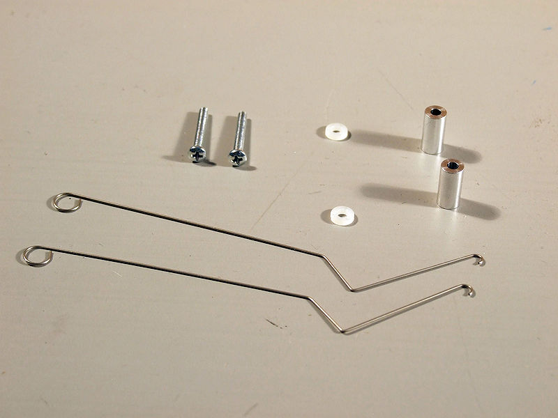
To build a mechanical "Switch" you will need 2x 1/2" metal standoffs, 2x plastic washers, 2x metal whiskers, and 2x screws (longer) for the mechanical part of the switch:
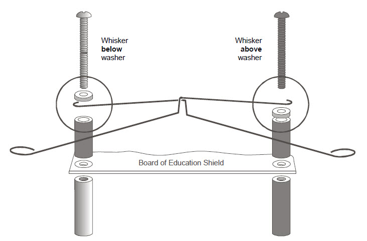
You will need to swap out the small screws holding the shield near the breadboard with the whiskers. In the end it should look like the image below.
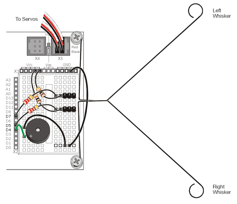
For the electrical circuit, you will need the two 3-pin male headers, two 10kΩ resistors (Brown-Black-Orange), two 220Ω resistors (Red-Red-Brown), and two jumper wires. Plug the components into the bread board so it looks like the following:
When the robot is in an open area and the whiskers are not touching anything, the switch is open. This means that the circuit is providing the digital input pin with a high logic level.
However, when the robot starts to drive into a wall, the whiskers get pushed in towards the pins in the breadboard. Once the whiskers have been push far enough, the whiskers contacnt the pins and thus close the switch. Since the whiskers are connected to the BOE Shield-Bot frame, which is in turn connected to ground, the whiskers bring the digital input pin to ground and a low logic level.
// Robotics with the BOE Shield - RoamingWithWhiskers
// Go forward.  Back up and turn if whiskers indicate BOE Shield bot bumped
// into something.

#include <Servo.h>                           // Include servo library

Servo servoLeft;                             // Declare left and right servos
Servo servoRight;

void setup()                                 // Built-in initialization block
{
  pinMode(7, INPUT);                         // Set right whisker pin to input
  pinMode(5, INPUT);                         // Set left whisker pin to input

  tone(4, 3000, 1000);                       // Play tone for 1 second
  delay(1000);                               // Delay to finish tone

  servoLeft.attach(13);                      // Attach left signal to pin 13
  servoRight.attach(12);                     // Attach right signal to pin 12
}

void loop()                                  // Main loop auto-repeats
{
  byte wLeft = digitalRead(5);               // Copy left result to wLeft
  byte wRight = digitalRead(7);              // Copy right result to wRight

  if((wLeft == 0) && (wRight == 0))          // If both whiskers contact
  {
    backward(1000);                          // Back up 1 second
    turnLeft(800);                           // Turn left about 120 degrees
  }
  else if(wLeft == 0)                        // If only left whisker contact
  {
    backward(1000);                          // Back up 1 second
    turnRight(400);                          // Turn right about 60 degrees
  }
  else if(wRight == 0)                       // If only right whisker contact
  {
    backward(1000);                          // Back up 1 second
    turnLeft(400);                           // Turn left about 60 degrees
  }
  else                                       // Otherwise, no whisker contact
  {
    forward(20);                             // Forward 1/50 of a second
  }
}

void forward(int time)                       // Forward function
{
  servoLeft.writeMicroseconds(1700);         // Left wheel counterclockwise
  servoRight.writeMicroseconds(1300);        // Right wheel clockwise
  delay(time);                               // Maneuver for time ms
}

void turnLeft(int time)                      // Left turn function
{
  servoLeft.writeMicroseconds(1300);         // Left wheel clockwise
  servoRight.writeMicroseconds(1300);        // Right wheel clockwise
  delay(time);                               // Maneuver for time ms
}

void turnRight(int time)                     // Right turn function
{
  servoLeft.writeMicroseconds(1700);         // Left wheel counterclockwise
  servoRight.writeMicroseconds(1700);        // Right wheel counterclockwise
  delay(time);                               // Maneuver for time ms
}

void backward(int time)                      // Backward function
{
  servoLeft.writeMicroseconds(1300);         // Left wheel clockwise
  servoRight.writeMicroseconds(1700);        // Right wheel counterclockwise
  delay(time);                               // Maneuver for time ms
}


