Acrob020: Rozdiel medzi revíziami
Zo stránky SensorWiki
Bez shrnutí editace |
Bez shrnutí editace |
||
| Riadok 1: | Riadok 1: | ||
== Navigating with whiskers == | |||
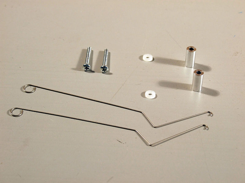
To build a mechanical "Switch" you will need 2x 1/2" metal standoffs, | |||
2x plastic washers, 2x metal whiskers, and 2x screws (longer) for the | |||
mechanical part of the switch: | |||
[[Image:AcrobWhiskersComponents.jpg]] | [[Image:AcrobWhiskersComponents.jpg]] | ||
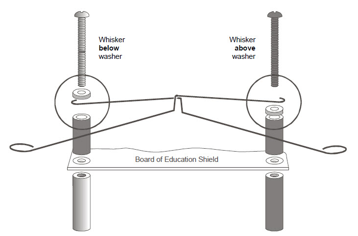
You will need to swap out the small screws holding the shield near the breadboard with the whiskers. In the end it should look like the image below. | |||
[[Image:AcrobWhiskersMechanical.jpg]] | [[Image:AcrobWhiskersMechanical.jpg]] | ||
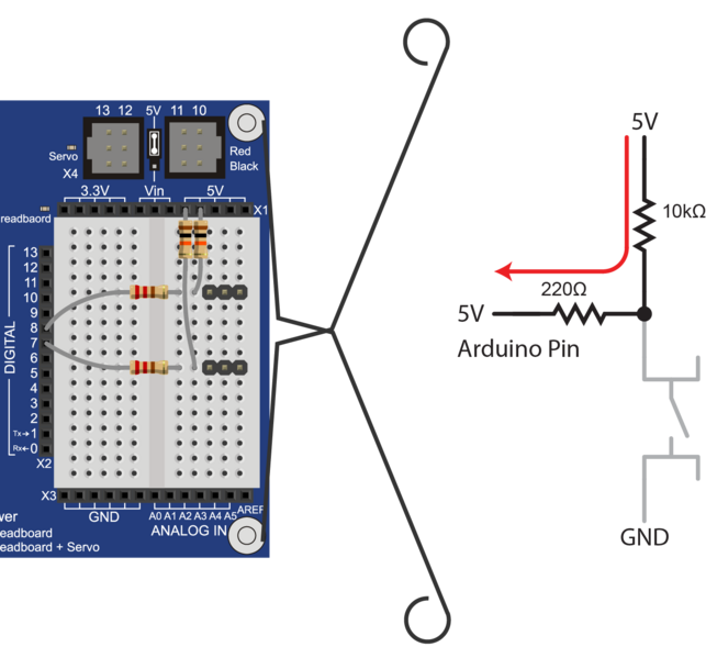
For the electrical circuit, you will need the two 3-pin male headers, | |||
two 10kΩ resistors (Brown-Black-Orange), two 220Ω resistors (Red-Red-Brown), | |||
and two jumper wires. Plug the components into the bread board so it looks like the following: | |||
[[Image:AcrobWhiskersElectrical.jpg]] | [[Image:AcrobWhiskersElectrical.jpg]] | ||
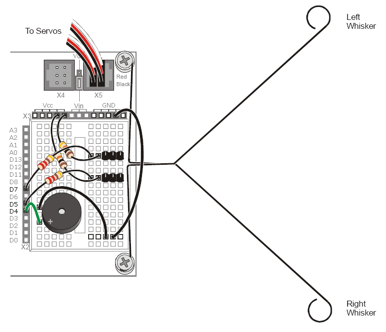
When the robot is in an open area and the whiskers are not touching anything, the switch is open. This means that the circuit is providing the digital input pin with a high logic level. | |||
However, when the robot starts to drive into a wall, the whiskers get pushed in towards the pins in the breadboard. Once the whiskers have been push far enough, the whiskers contacnt the pins and thus close the switch. Since the whiskers are connected to the BOE Shield-Bot frame, which is in turn connected to ground, the whiskers bring the digital input pin to ground and a low logic level. | |||
[[Obrázok:AcrobWhiskers.png]] | [[Obrázok:AcrobWhiskers.png]] | ||
Verzia z 23:04, 18. november 2015
To build a mechanical "Switch" you will need 2x 1/2" metal standoffs, 2x plastic washers, 2x metal whiskers, and 2x screws (longer) for the mechanical part of the switch:
You will need to swap out the small screws holding the shield near the breadboard with the whiskers. In the end it should look like the image below.
For the electrical circuit, you will need the two 3-pin male headers, two 10kΩ resistors (Brown-Black-Orange), two 220Ω resistors (Red-Red-Brown), and two jumper wires. Plug the components into the bread board so it looks like the following:
When the robot is in an open area and the whiskers are not touching anything, the switch is open. This means that the circuit is providing the digital input pin with a high logic level.
However, when the robot starts to drive into a wall, the whiskers get pushed in towards the pins in the breadboard. Once the whiskers have been push far enough, the whiskers contacnt the pins and thus close the switch. Since the whiskers are connected to the BOE Shield-Bot frame, which is in turn connected to ground, the whiskers bring the digital input pin to ground and a low logic level.


