MEMS Cvičenie 8: Rozdiel medzi revíziami
Zo stránky SensorWiki
| Riadok 62: | Riadok 62: | ||
--> | --> | ||
== | == Vzorový program na meranie == | ||
<source lang="c"> | <source lang="c"> | ||
Verzia z 16:50, 19. apríl 2022
Ultrazvukové snímače
Zadanie pre ultrazvukový snímač
- Zmerajte dobu odozvy UZ snímača pri odraze od prekážky
- Prepočítajte zmeranú dobu odozvy na vzdialenosť v cm (výpočet)
- Pridajte kompenzáciu na vplyv teploty (výpočet)
- Zmerajte prevodovú charakteristiku snímača s kompenzáciou a bez kompenzácie (tabuľka + grafická závislosť zmeranej vzdialenosti od skutočnej)
- Zmerajte kritický uhol pre vzdialenosť 50, 100 a 150 cm.
- Zmerajte vyžarovaciu charakteristiku senzora
- Zmerajte minimálnu veľkosť detekovanej prekážky
- Určte minimálnu a maximálnu detekovanú vzdialenosť
- Nájdete objekt neviditeľný pre tento senzor?
Ultrasonic sensor for distance measurement

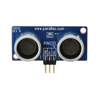
Na tomto cvičení budeme používať ultrazvukový senzor firmy Parallax s názvom PING))) Ultrasonic sensor.
- PING)))™ Documentation v1.6 (.pdf)
Vlastnosti:
- Rozsah merania 2 cm až 3 m
- Ovládanie cez jeden jediný pin
- Indikačná LED dióda signalizuje začiatok merania
- Spotreba 20 mA
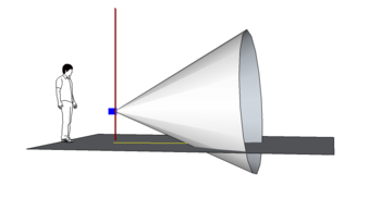
- Úzky vyžarovací uhol
Technické údaje:
- Napájanie: +5 VDC
- Spustenie merania: kladný TTL impulz
- Rozmery: 22 x 46 x 16 mm
- Pracovná teplota: 0 až +70 °C
Princíp činnosti
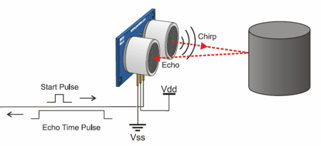
Snímač Ping meria vzdialenosť podobne ako sonar; najskôr sa vysiela ultrazvukový (frekvencia je nad hranicou ľudského sluchu) impulz (chirp) a vzdialenosť k cieľu sa určuje meraním času, ktorý je potrebný na zachytenie ozveny (echa). Výstupom zo snímača je impulz s premenlivou šírkou, ktorý zodpovedá vzdialenosti k cieľu.


Senzor detekuje objekty tak, že vyšle krátky ultrazvukový signál a potom "počúva" ozvenu. Celý proces riadi mikroprocesor. Najskôr vyšle krátky impulz, ktorý spustí odvysielanie krátkeho 40 kHz (ultrazvuk) impulzu.
Ten sa šíri vzduchom, narazí na objekt a potom sa odrazí späť k snímaču. Medzitým mikroprocesor otočí smer na riadiacom pine, prepne sa do vstupného režimu a počíta, za ako dlho zachytí odozvu (echo). Čas medzi vyslaním a prijatím impulzu je proporcionálna k vzdialenosti objektu.
Vzorový program na meranie
int pingPin = 11;

void setup()
{
  Serial.begin(9600);
}

void loop()
{
  long duration;

  // The PING))) is triggered by a HIGH pulse of 2 or more microseconds.
  // We give a short LOW pulse beforehand to ensure a clean HIGH pulse.

  pinMode(pingPin, OUTPUT);
  digitalWrite(pingPin, LOW);
  delayMicroseconds(2);
  digitalWrite(pingPin, HIGH);
  delayMicroseconds(5);
  digitalWrite(pingPin, LOW);

  // The same pin is used to read the signal from the PING))): a HIGH
  // pulse whose duration is the time (in microseconds) from the sending
  // of the ping to the reception of its echo off of an object.

  pinMode(pingPin, INPUT);
  duration = pulseIn(pingPin, HIGH);

  Serial.print(duration);
  Serial.print("us");
  Serial.println();

  delay(100);
}
pulseIn()
Description
Reads a pulse (either HIGH or LOW) on a pin. For example, if value is HIGH, pulseIn() waits for the pin to go HIGH, starts timing, then waits for the pin to go LOW and stops timing. Returns the length of the pulse in microseconds. Gives up and returns 0 if no pulse starts within a specified time out.
The timing of this function has been determined empirically and will probably show errors in longer pulses. Works on pulses from 10 microseconds to 3 minutes in length.
Syntax
pulseIn(pin, value) pulseIn(pin, value, timeout)
Parameters
pin: the number of the pin on which you want to read the pulse. (int)
value: type of pulse to read: either HIGH or LOW. (int)
timeout (optional): the number of microseconds to wait for the pulse to start; default is one second (unsigned long)
Returns
the length of the pulse (in microseconds) or 0 if no pulse started before the timeout (unsigned long)
Program na meranie a zobrazovanie na LCD displej
(kliknutím rozbaliť / zbaliť)
/*
  LiquidCrystal Library - Hello World

 Demonstrates the use a 8x2 LCD display.

   The circuit:
 * LCD RS pin to digital pin 3
 * LCD R/W pin to digital pin 2
 * LCD Enable pin to digital pin 1
 * LCD D4 pin to digital pin 4
 * LCD D5 pin to digital pin 5
 * LCD D6 pin to digital pin 6
 * LCD D7 pin to digital pin 7
 */

#include <LiquidCrystal.h>           // include the library

// initialize the library with the numbers of the interface pins
//  LiquidCrystal(RS, RW, EN, D4, D5, D6, D7)
LiquidCrystal lcd( 3,  2,  1,  4,  5,  6,  7);
int pingPin = 8;

const int trigPin = 11;
const int echoPin = 12;


void setup() {
  // set up the LCD's number of columns and rows:
  lcd.begin(8, 2);
  // Print a message to the LCD.
  lcd.print("Time[us]");

  pinMode(trigPin, OUTPUT);
  pinMode(echoPin, INPUT);
}

void loop() {

  long duration1;
  long duration2;
   int distanceCm;

     // The PING))) is triggered by a HIGH pulse of 2 or more microseconds.
  // We give a short LOW pulse beforehand to ensure a clean HIGH pulse.

  pinMode(pingPin, OUTPUT);
  digitalWrite(pingPin, LOW);
  delayMicroseconds(2);
  digitalWrite(pingPin, HIGH);
  delayMicroseconds(5);
  digitalWrite(pingPin, LOW);

  // The same pin is used to read the signal from the PING))): a HIGH
  // pulse whose duration is the time (in microseconds) from the sending
  // of the ping to the reception of its echo off of an object.

  pinMode(pingPin, INPUT);
  duration1 = pulseIn(pingPin, HIGH);

//  // Simillar for the HSR-04 sensor
//  digitalWrite(trigPin, LOW);
//  delayMicroseconds(2);
//  digitalWrite(trigPin, HIGH);
//  delayMicroseconds(10);
//  digitalWrite(trigPin, LOW);
//  duration2 = pulseIn(echoPin, HIGH);

  // set the cursor to column 0, line 1
  // (note: line 1 is the second row, since counting begins with 0):
  lcd.setCursor(0, 1);
  lcd.print("        ");
  lcd.setCursor(0, 1);
  // print the number of seconds since reset:
  //lcd.print(millis()/1000);

  lcd.print(duration1);
//  distanceCm= duration2*0.034/2;
//  lcd.print(distanceCm);

  delay(200);

}
Connection
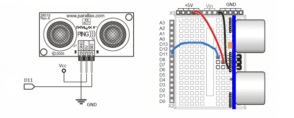
Interfacing to the microcontrollers is a snap: a single (shared) I/O pin is use to trigger the Ping sensor and "listen" for the echo return pulse. An onboard three-pin header allows the PING))) to be plugged into a solderless breadboard (on an Acrob, for example), and to be connected to its host through a standard three-pin servo extension cable.

Sources of errors
Air Temperature
Changing environmental conditions are the main source of the differences. Many quantities influences measurement
including temperature, humidity, turbulences, pressure and damping. Main source of error is air circulation and
temperature. Many equations appears in literature, two of them are mentioned here:
where
- - speed of the sound at 0° C and 0% RH (c0 = 331,5 [m/s]),
- - temperature coefficient of the speed (@ 0° C), γ = 1.83 10-3 [°C-1],
- - humidity constatnt (AV = 2,2 . 10^-4, for 50 ÷ 200 kHz),
- - relative humidity of air [%],
- - air temperature [°C].
For practical purposes we can abandon humidity influences and then simplified formula applies:
The percent error over the sensor’s operating range of 0 to 70 ° C is significant, in the magnitude of 11 to 12 percent. The use of conversion constants to account for air temperature may be incorporated into your program.
Potrebujete pravítko, alebo uhlomer?

Ak nemôžete prísť na cvičenie do laboratória, aspoň čiastočne si ho môžete nahradiť simulátorom TinkerCAD.
Nepovinná domáca úloha
Mobilný robot na Marse je natočený smerom na východ. Ultrazvukový otočný senzor zmeral
objekty, ktoré treba preskúmať v nasledovných troch smeroch (uvedená je vždy séria niekoľkých meraní v stupňoch):
- a) 85, 95, 110, 90
- b) 350, 360, 0, 10
- c) 350, 360, 10, 360
Všetky tri sa nachádzajú vo vzdialenosti 100 m. Vypočítajte priemernú hodnotu a smerodajnú odchýlku a na základe
toho rozhodnite:
Ktorým smerom sa má vydať na prieskum, aby minul čo najmenej času a energie na otáčanie?


![{\displaystyle (2)\qquad c=c_{0}+0,6\vartheta [m/s]}](https://wikimedia.org/api/rest_v1/media/math/render/svg/7d9bf0a18707e5f1fa7b30a2278c1c11431bbf4c)