AVR StudioTutorial: Rozdiel medzi revíziami
Zo stránky SensorWiki
Nová stránka: for version 4 == Starting AVR Studio == * Start the AVR Studio program by clicking on: Start->Programs->ATMEL AVR Tools->AVR Studio 3.56 Once the program has started, you... |
Bez shrnutí editace |
||
| (12 medziľahlých úprav od rovnakého používateľa nie je zobrazených.) | |||
| Riadok 7: | Riadok 7: | ||
* Start the AVR Studio program by clicking on: | * Start the AVR Studio program by clicking on: | ||
Start->Programs->ATMEL AVR Tools->AVR Studio | Start->Programs->ATMEL AVR Tools->AVR Studio 4 | ||
Once the program has started, you will be looking at a screen like this. | Once the program has started, you will be looking at a screen like this. | ||
[[Obrázok:AVR_Studio_Screen01.png]] | [[Obrázok:AVR_Studio_Screen01.png|center]] | ||
== Creating a New Project == | |||
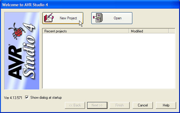
Immediately after the start, the popup window will appear. You can open an old project or create a new one. To create a new project, select "New Project". | |||
[[Obrázok:AVR_Studio_Screen02.png|center]] | |||
The dialog box shown in the next figure appears. In this dialog box you should enter the type of the project, its name and location. | |||
[[Obrázok:AVR_Studio_Screen03.png|center]] | |||
First, we have to select the Project type: | |||
* '''Atmel AVR Assembler''': This informs AVR Studio that is should use the built-in Assembler when compiling the project. We'll use this option in the following example. | |||
* AVR GCC compiler: This option enables the user to use an external gcc compiler when compiling and linking the project. | |||
Select the "Atmel AVR Assembler" Project type. | |||
Next, we have to assign a name to our project. | |||
We choose the name '''Example1''' here, but this could of course be an arbitrary name. | |||
Wa also choose the name of the main source file as '''main.asm''', but this usually can be the same name as the project. | |||
Next you'll have to select the project location. This is the location where AVR Studio will store all files associated | |||
with the project. We have used the location D:\ as the folder. If the folder does not exist, AVR Studio will automatically | |||
create it without any further notification. | |||
Now press the 'Next' button to continue. | |||
== Selecting the Device == | |||
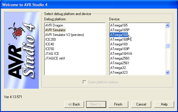
You will now get the window shown below. Since we do not have an In-Circuit Emulator attached, | |||
select '''AVR Simulator''' as Debug platform. In the Device list window you select the device for which you want | |||
to simulate the code. Select ATmega168 as the device. | |||
[[Obrázok:AVR_Studio_Screen04.png|center]] | |||
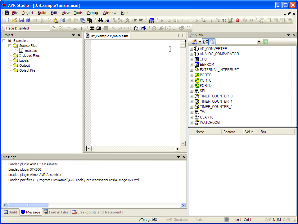
Project is now ready and full IDE window is opened. | |||
[[Obrázok:AVR_Studio_Screen05.png|center]] | |||
== Editing the Assembler file == | |||
The whole project will now appear and look as shown in the figure below. In this view, you'll see all files associated with your project. | |||
It will be empty at this point. The file is empty and you'll have to manually enter the code, or you may Copy and Paste the code directly into | |||
the editor window. | |||
[[Obrázok:AVR_Studio_Screen06.png|center]] | |||
Don't forget to save Your source file befor any other operations with it! | |||
== Assemble the Source Code == | |||
This example requires the file m168def.inc to assemble properly. This file is the definition file for the ATmega168, | |||
and contains definitions for the microcontroller needed by the assembler. | |||
The next step now is to assemble the file. This is done by selecting "Assemble" from the "Project" menu, or by pressing <F7>. | |||
[[Obrázok:AVR_Studio_Screen07.png|center]] | |||
The "Project Output" window will show information from the assembler. From this window we can see that the code | |||
is 28 bytes, and assembly was completed with no errors. | |||
We are now ready to advance to the next step, which is running the code in simulator mode. | |||
== Simulating the Code == | |||
At this point we have generated the files needed to simulate the code. | |||
To start running the code, select "Start debug" from the "Debug" menu, or press <F11>. | |||
=== Instruction Pointer === | |||
Now take a look in the editor view, you'll see that a yellow right-arrow has appeared in the left margin of the code. This arrow indicates the position of the program counter. In other words, it points to the next instruction to be executed. What we want to do now is to set up the IO views so that we can have a closer look at what is happening on the Port B and registers during program execution. Since we have selected the ATmega168 during the Simulator options setting this IO view will be opened automatically. | |||
[[Obrázok:AVR_Studio_Screen08.png|center]] | |||
=== I/O View === | |||
The IO Window is used to inspect and modify the contents of the I/O registers in the execution target. The standard configuration gives you a quick overview of the hardware with the ability to expand particular items for more information. | |||
Open the "Port B" tree by double clicking on the icon for the port. It will now expand and show all registers associated with Port B, these are: Port B Data register (PORTB), Data Direction (DDRB) and Input Pins (PINB). As shown each bit in the registers are represented by a checkbox. A logical 'zero' (0) is represented by a checkbox without a tick and a logical 'one' (1) is represented by a checkbox with a tick. These checkboxes will be updated during program execution, and show the current state of every bit. You may also set and clear these bits by clicking on the appropriate checkbox at any time during the program execution. | |||
=== Single Stepping the Program === | |||
There are two commands to single step through the code. These are "Step Over" <F10> and "Trace Into" <F11>. The difference between these commands is that <F10> do not trace into subroutines. Since our example does not contain any subroutines, there is no difference between the operation of these commands in this example. | |||
Now single step down to the last line of code (rjmp loop) by repeatedly pressing the <F11> key or by selecting "Trace Into" from the "Debug" menu. Notice how the colour changes from black to red on the registers that change value. This makes it easier to identify which registers change value on each instruction. Continue pressing the <F11> key and see how the binary value in Port B is increased. | |||
=== Setting Breakpoints === | |||
Breakpoints are a method of halting execution flow. By adding a breakpoint in the assembly code we can run run the program at full speed, and it will be stopped at the line with the breakpoint. By now you have noticed that you have to press <F11> three times to go through the loop once. We will add a breakpoint at the rjmp loop instruction to show how this can be used to speed up the debug process. Place the cursor on the rjmp loop instruction in the source view window and press <F9> (or the "Toggle Program Breakpoint" in the "Breakpoints" menu ). A red square will appear in the left margin of the source view window as shown. By pressing <F5> or "Go" from the "Debug" menu the program will start running and break (stop) at the intruction with the breakpoint. | |||
fig17.jpg | |||
=== Modifying the Code === | |||
Now we want the program to count down instead of up. To make this change we'll have to edit the source code. Place the cursor in the source view, and change the inc to a dec instruction. If you now press <F5> (Go) the following dialog box will appear. This box indicates that one of the source files has been changed, and that the project should be rebuilt. Press "Yes". | |||
fig18.jpg | |||
The Project will now be rebuilt, and the instruction pointer will start at the first line of code. Notice how the breakpoint is remembered. | |||
=== Opening the Watch View === | |||
Open the Watch window by selecting "Watch" from the "View" menu. | |||
fig19.jpg | |||
Variables that are defined (by the .def directive) can be placed in the Watch view. The only defined variable in this code is the temp variable. Right-click the "Watches" window and select "Add Watch". Type in the variable name temp at the cursor and then press the Enter key. As we continue to run through the program the temp variable will constantly be updated during program execution. | |||
fig20.jpg | |||
=== Setting up the Processor View === | |||
Now we will set up the Processor view. Open this view by selecting "Processor" from the "View" menu. | |||
fig21.jpg | |||
This view shows processor specific information like the state of the Flags register and the current value of the different pointers. In this view you will also find a Cycle Counter and a StopWatch. These are very useful if you wish to measure the length of a loop or how much time a specific subroutine uses. We will not use this view directly in this example, but it provides a lot of useful information during debugging of a project. | |||
fig22.jpg | |||
=== Saving the Project === | |||
Before exiting AVR Studio we will save our project. AVR Studio will remember where the views are placed and will use this setting when opening the project later. To save the project select "Save" from the "Project" menu. | |||
Back to Contents | |||
[[Category:MMP]] | |||
Aktuálna revízia z 07:48, 24. september 2010
for version 4
Starting AVR Studio
- Start the AVR Studio program by clicking on:
Start->Programs->ATMEL AVR Tools->AVR Studio 4
Once the program has started, you will be looking at a screen like this.

Creating a New Project
Immediately after the start, the popup window will appear. You can open an old project or create a new one. To create a new project, select "New Project".
The dialog box shown in the next figure appears. In this dialog box you should enter the type of the project, its name and location.
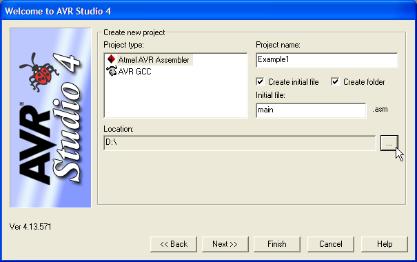
First, we have to select the Project type:
- Atmel AVR Assembler: This informs AVR Studio that is should use the built-in Assembler when compiling the project. We'll use this option in the following example.
- AVR GCC compiler: This option enables the user to use an external gcc compiler when compiling and linking the project.
Select the "Atmel AVR Assembler" Project type.
Next, we have to assign a name to our project. We choose the name Example1 here, but this could of course be an arbitrary name. Wa also choose the name of the main source file as main.asm, but this usually can be the same name as the project.
Next you'll have to select the project location. This is the location where AVR Studio will store all files associated with the project. We have used the location D:\ as the folder. If the folder does not exist, AVR Studio will automatically create it without any further notification.
Now press the 'Next' button to continue.
Selecting the Device
You will now get the window shown below. Since we do not have an In-Circuit Emulator attached, select AVR Simulator as Debug platform. In the Device list window you select the device for which you want to simulate the code. Select ATmega168 as the device.
Project is now ready and full IDE window is opened.
Editing the Assembler file
The whole project will now appear and look as shown in the figure below. In this view, you'll see all files associated with your project. It will be empty at this point. The file is empty and you'll have to manually enter the code, or you may Copy and Paste the code directly into the editor window.
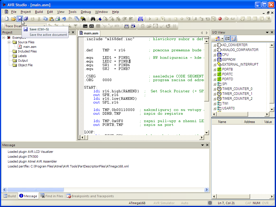
Don't forget to save Your source file befor any other operations with it!
Assemble the Source Code
This example requires the file m168def.inc to assemble properly. This file is the definition file for the ATmega168, and contains definitions for the microcontroller needed by the assembler.
The next step now is to assemble the file. This is done by selecting "Assemble" from the "Project" menu, or by pressing <F7>.
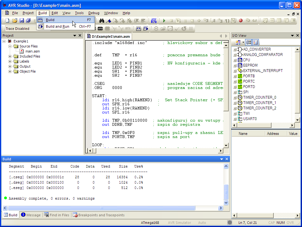
The "Project Output" window will show information from the assembler. From this window we can see that the code is 28 bytes, and assembly was completed with no errors.
We are now ready to advance to the next step, which is running the code in simulator mode.
Simulating the Code
At this point we have generated the files needed to simulate the code. To start running the code, select "Start debug" from the "Debug" menu, or press <F11>.
Instruction Pointer
Now take a look in the editor view, you'll see that a yellow right-arrow has appeared in the left margin of the code. This arrow indicates the position of the program counter. In other words, it points to the next instruction to be executed. What we want to do now is to set up the IO views so that we can have a closer look at what is happening on the Port B and registers during program execution. Since we have selected the ATmega168 during the Simulator options setting this IO view will be opened automatically.
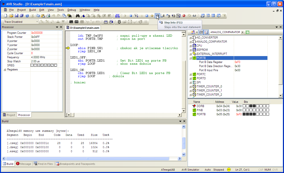
I/O View
The IO Window is used to inspect and modify the contents of the I/O registers in the execution target. The standard configuration gives you a quick overview of the hardware with the ability to expand particular items for more information.
Open the "Port B" tree by double clicking on the icon for the port. It will now expand and show all registers associated with Port B, these are: Port B Data register (PORTB), Data Direction (DDRB) and Input Pins (PINB). As shown each bit in the registers are represented by a checkbox. A logical 'zero' (0) is represented by a checkbox without a tick and a logical 'one' (1) is represented by a checkbox with a tick. These checkboxes will be updated during program execution, and show the current state of every bit. You may also set and clear these bits by clicking on the appropriate checkbox at any time during the program execution.
Single Stepping the Program
There are two commands to single step through the code. These are "Step Over" <F10> and "Trace Into" <F11>. The difference between these commands is that <F10> do not trace into subroutines. Since our example does not contain any subroutines, there is no difference between the operation of these commands in this example.
Now single step down to the last line of code (rjmp loop) by repeatedly pressing the <F11> key or by selecting "Trace Into" from the "Debug" menu. Notice how the colour changes from black to red on the registers that change value. This makes it easier to identify which registers change value on each instruction. Continue pressing the <F11> key and see how the binary value in Port B is increased.
Setting Breakpoints
Breakpoints are a method of halting execution flow. By adding a breakpoint in the assembly code we can run run the program at full speed, and it will be stopped at the line with the breakpoint. By now you have noticed that you have to press <F11> three times to go through the loop once. We will add a breakpoint at the rjmp loop instruction to show how this can be used to speed up the debug process. Place the cursor on the rjmp loop instruction in the source view window and press <F9> (or the "Toggle Program Breakpoint" in the "Breakpoints" menu ). A red square will appear in the left margin of the source view window as shown. By pressing <F5> or "Go" from the "Debug" menu the program will start running and break (stop) at the intruction with the breakpoint.
fig17.jpg
Modifying the Code
Now we want the program to count down instead of up. To make this change we'll have to edit the source code. Place the cursor in the source view, and change the inc to a dec instruction. If you now press <F5> (Go) the following dialog box will appear. This box indicates that one of the source files has been changed, and that the project should be rebuilt. Press "Yes".
fig18.jpg
The Project will now be rebuilt, and the instruction pointer will start at the first line of code. Notice how the breakpoint is remembered.
Opening the Watch View
Open the Watch window by selecting "Watch" from the "View" menu.
fig19.jpg
Variables that are defined (by the .def directive) can be placed in the Watch view. The only defined variable in this code is the temp variable. Right-click the "Watches" window and select "Add Watch". Type in the variable name temp at the cursor and then press the Enter key. As we continue to run through the program the temp variable will constantly be updated during program execution.
fig20.jpg
Setting up the Processor View
Now we will set up the Processor view. Open this view by selecting "Processor" from the "View" menu.
fig21.jpg
This view shows processor specific information like the state of the Flags register and the current value of the different pointers. In this view you will also find a Cycle Counter and a StopWatch. These are very useful if you wish to measure the length of a loop or how much time a specific subroutine uses. We will not use this view directly in this example, but it provides a lot of useful information during debugging of a project.
fig22.jpg
Saving the Project
Before exiting AVR Studio we will save our project. AVR Studio will remember where the views are placed and will use this setting when opening the project later. To save the project select "Save" from the "Project" menu.
Back to Contents