7-segmentový displej na futbal: Rozdiel medzi revíziami
Zo stránky SensorWiki
| (20 medziľahlých úprav od rovnakého používateľa nie je zobrazených.) | |||
| Riadok 10: | Riadok 10: | ||
'''Literatúra:''' | '''Literatúra:''' | ||
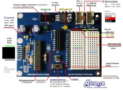
* [http://ap.urpi.fei.stuba.sk/sensorwiki/index.php/Acrob_technical_description Dokumentácia k doske Acrob] | * [http://ap.urpi.fei.stuba.sk/sensorwiki/index.php/Acrob_technical_description Dokumentácia k doske Acrob] | ||
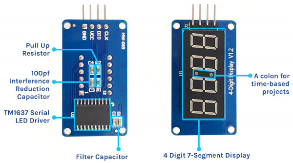
* [https://github.com/avishorp/TM1637 Dokumentacia k TM1637 displeji] | |||
* [https://github.com/TeWu/TM1637 Kniznice k TM1637 displeji] | |||
| Riadok 26: | Riadok 28: | ||
=== Algoritmus a program === | === Algoritmus a program === | ||
Tento program sme vytvorili na ovládanie 7 segmentového displeja pomocou tlačidiel a následného zobrazovania futbalového skóre pomocou tlačidiel. Najprv sme si vytvorili knižnicu do ktorej sme uložili čísla od 0-9 na zobrazenie čísiel pomocou svietiacich a zhasnutých segmentov. Následne sme si vytvorili funkcie na zapnutie a vypnutie komunikácie. | Tento program sme vytvorili na ovládanie 7 segmentového displeja pomocou tlačidiel a následného zobrazovania futbalového skóre pomocou tlačidiel. Najprv sme si vytvorili knižnicu do ktorej sme uložili čísla od 0-9 na zobrazenie čísiel pomocou svietiacich a zhasnutých segmentov. Následne sme si vytvorili funkcie na zapnutie a vypnutie komunikácie. Potom sme si vytvorili funkcie na inicializáciu, nastavenie segmentov a ich následné zobrazenie. Všetky tieto funkcie sme uložili do uart.c (resp. SemProj_uart.c). | ||
Nakoniec sme pre INT0 a INT1 spravili funkcie, jedna pre ľavú stranu a druhá pre pravú stranu, v ktorých po stlačení tlačidla nastalo zvýšenie hodnoty o 1, kde ak sme dosiahli číslo 99 a zvýšili sme ho, číslo sa nám resetovalo naspäť na 0, keďže na číselné hodnoty sme mali iba 2 7 - segmentové displeje. Keď sme mali všetky tieto funkcie zadefinované, v hlavnej časti programu sme CLK, DIO aj všetky ostatné piny nastavili opäť ako input, povolili sme INT0 a INT1 takisto sei(). | |||
Následne vo while funkcii sme už len dané čísla, ktoré boli uložené v counter_left a counter_right zobrazovali pomocou našej funkcie pre zobrazenie čísla na 7 segmentovke, kde sme pozíciu čísel nastavili na pravú 7 segmentovku z dvojice (čiže celkovo 2. a 4. 7 segmentovka) a po zvýšení čísla na 10 a viac sa začali využívať obe 7 segmentové displeje pre daný tím. Po stlačení tlačidla RESET sa hodnoty v counter_left a counter_right vynulovali a opäť sa využívali iba pravé 7 segmentovky z dvojice. Takto to funguje donekonečna. | Následne vo while funkcii sme už len dané čísla, ktoré boli uložené v counter_left a counter_right zobrazovali pomocou našej funkcie pre zobrazenie čísla na 7 segmentovke, kde sme pozíciu čísel nastavili na pravú 7 segmentovku z dvojice (čiže celkovo 2. a 4. 7 segmentovka) a po zvýšení čísla na 10 a viac sa začali využívať obe 7 segmentové displeje pre daný tím. Po stlačení tlačidla RESET sa hodnoty v counter_left a counter_right vynulovali a opäť sa využívali iba pravé 7 segmentovky z dvojice. Takto to funguje donekonečna. | ||
| Riadok 39: | Riadok 41: | ||
#include <util/delay.h> | #include <util/delay.h> | ||
#include <avr/interrupt.h> | #include <avr/interrupt.h> | ||
#include "uart.h" | |||
#define CLK PD5 // CLK -> pin 5 | #define CLK PD5 // CLK -> pin 5 | ||
| Riadok 48: | Riadok 51: | ||
#define LEFT_START_STOP_PIN PD2 // | #define LEFT_START_STOP_PIN PD2 // Tlacidlo pre lavy tim | ||
#define RIGHT_START_STOP_PIN PD3 // | #define RIGHT_START_STOP_PIN PD3 // Tlacidlo pre pravy tim | ||
#define RESTART_PIN PD6 // | #define RESTART_PIN PD6 // Tlacidlo na vynulovanie skore | ||
| Riadok 56: | Riadok 59: | ||
volatile uint8_t count_left = 0; // | volatile uint8_t count_left = 0; // Pocitadlo skore pre lavu dvojicu 7 segmentoviek | ||
volatile uint8_t count_right = 0; // | volatile uint8_t count_right = 0; // Pocitadlo skore pre pravu dvojicu 7 segmentoviek | ||
// External interrupt 0 ( | // External interrupt 0 (Tlacidlo pre lavy tim) | ||
ISR (INT0_vect) | ISR (INT0_vect) | ||
{ | { | ||
| Riadok 68: | Riadok 71: | ||
_delay_ms(10); | _delay_ms(10); | ||
if(bit_is_clear(PIND, LEFT_START_STOP_PIN)){ | if(bit_is_clear(PIND, LEFT_START_STOP_PIN)){ | ||
// | // Zvysuje skore laveho time a pri dosiahnuti hodnoty 100 zresetuje hodnotu na 0 | ||
count_left++; | count_left++; | ||
| Riadok 76: | Riadok 79: | ||
} | } | ||
// External interrupt 1 ( | // External interrupt 1 (tlacidlo pre pravy tim) | ||
ISR (INT1_vect) | ISR (INT1_vect) | ||
{ | { | ||
_delay_ms(10); | _delay_ms(10); | ||
if(bit_is_clear(PIND, RIGHT_START_STOP_PIN)){ | if(bit_is_clear(PIND, RIGHT_START_STOP_PIN)){ | ||
// | // Zvysuje skore praveho time a pri dosiahnuti hodnoty 100 zresetuje hodnotu na 0 | ||
count_right++; | count_right++; | ||
if (count_right >= 100) count_right = 0; | if (count_right >= 100) count_right = 0; | ||
| Riadok 91: | Riadok 94: | ||
int main(void){ | int main(void){ | ||
clear_bit(DDRD, CLK); // | clear_bit(DDRD, CLK); // Nastavenie CLK ako input | ||
set_bit(PORTD, CLK); // CLK | set_bit(PORTD, CLK); // CLK ako input pull-up on | ||
clear_bit(DDRD, DIO); // | clear_bit(DDRD, DIO); // Nastavenie DIO ako input | ||
set_bit(PORTD, DIO); // DIO | set_bit(PORTD, DIO); // DIO ako input pull-up o | ||
clear_bit(DDRD, LEFT_START_STOP_PIN); // | clear_bit(DDRD, LEFT_START_STOP_PIN); // Nastavenie LEFT_START_STOP_PIN ako input | ||
set_bit(PORTD, LEFT_START_STOP_PIN); // LEFT_START_STOP_PIN | set_bit(PORTD, LEFT_START_STOP_PIN); // LEFT_START_STOP_PIN ako input pull-up on | ||
clear_bit(DDRD, RIGHT_START_STOP_PIN); // | clear_bit(DDRD, RIGHT_START_STOP_PIN); // Nastavenie RIGHT_START_STOP_PIN ako input | ||
set_bit(PORTD, RIGHT_START_STOP_PIN); // RIGHT_START_STOP_PIN | set_bit(PORTD, RIGHT_START_STOP_PIN); // RIGHT_START_STOP_PIN ako input pull-up on | ||
clear_bit(DDRD, RESTART_PIN); // | clear_bit(DDRD, RESTART_PIN); // Nastavenie RESET_PIN ako input | ||
set_bit(PORTD, RESTART_PIN); // RESET_PIN | set_bit(PORTD, RESTART_PIN); // RESET_PIN ako input pull-up on | ||
uint8_t data[] = { 0, 0, 0, 0 }; | uint8_t data[] = { 0, 0, 0, 0 }; | ||
| Riadok 110: | Riadok 113: | ||
EIMSK = 0b00000011; // | EIMSK = 0b00000011; // Povolenie INT0, INT1 | ||
EICRA = 0b00001010; // | EICRA = 0b00001010; // Zaznamenanie dobeznej hrany na oboch pinoch | ||
sei(); // | sei(); // Povolit prerusenia | ||
| Riadok 119: | Riadok 122: | ||
while (1) { | while (1) { | ||
if (bit_is_clear(PIND, RESTART_PIN)) { | if (bit_is_clear(PIND, RESTART_PIN)) { | ||
// | // Spusti reset | ||
count_left = 0; // | count_left = 0; // Resetuje skore laveho timu | ||
count_right = 0; // | count_right = 0; // Resetuje skore praveho timu | ||
} | } | ||
// | // Zobrazenie skore laveho timu na lavych 2 7 segmentovkach a skore praveho timu na pravych 2 7 segmentovkach | ||
display_number_segment(count_right, 0, 2, 2); | display_number_segment(count_right, 0, 2, 2); | ||
| Riadok 136: | Riadok 139: | ||
return 0; | return 0; | ||
} | } | ||
}</source></tab> | </source></tab> | ||
<tab name="SemProj_uart.c"><source lang="c++" style="background: LightYellow;"> | |||
#include <avr/io.h> | |||
#include <util/delay.h> | |||
#include "uart.h" | |||
#define CLK PD5 // CLK -> pin 5 portD.5 | |||
#define DIO PD4 // DIO -> pin 4 portD.4 | |||
#define BIT_DELAY 100 // Delay 100ms | |||
// Define for TM1637 | |||
#define TM1637_I2C_COMM1 0x40 | |||
#define TM1637_I2C_COMM2 0xC0 | |||
#define TM1637_I2C_COMM3 0x80 | |||
// Nastavenie cisiel na 7 segmentovom displeji | |||
const uint8_t digitToSegment[] = { | |||
// XGFEDCBA | |||
0b00111111, // 0 | |||
0b00000110, // 1 | |||
0b01011011, // 2 | |||
0b01001111, // 3 | |||
0b01100110, // 4 | |||
0b01101101, // 5 | |||
0b01111101, // 6 | |||
0b00000111, // 7 | |||
0b01111111, // 8 | |||
0b01101111, // 9 | |||
0b01110111, // A | |||
0b01111100, // b | |||
0b00111001, // C | |||
0b01011110, // d | |||
0b01111001, // E | |||
0b01110001 // F | |||
}; | |||
uint8_t brightness = (0x7 & 0x7) | 0x08; | |||
static const uint8_t minusSegments = 0b01000000; | |||
int inicialize_bit(uint8_t byte){ | |||
uint8_t data = byte; | |||
// 8 Data Bits | |||
for(uint8_t i = 0; i < 8; i++) { | |||
// CLK low | |||
set_bit(DDRD, CLK); | |||
clear_bit(PORTD, CLK); | |||
_delay_us(BIT_DELAY); | |||
// Set data bit | |||
if (data & 0x01){ | |||
clear_bit(DDRD, DIO); // Nastavenie DIO ako input | |||
set_bit(PORTD, DIO); // DIO ako input pull-up on | |||
} else{ | |||
set_bit(DDRD, DIO); // Nastavenie DIO ako output | |||
clear_bit(PORTD, DIO); // Nastavenie DIO low | |||
} | |||
_delay_us(BIT_DELAY); | |||
// CLK high | |||
clear_bit(DDRD, CLK); // Nastavenie CLK ako input | |||
set_bit(PORTD, CLK); // CLK ako input pull-up on | |||
_delay_us(BIT_DELAY); | |||
data = data >> 1; | |||
} | |||
// Wait for acknowledge | |||
// CLK to zero | |||
set_bit(DDRD, CLK); // Nastavenie CLK ako output | |||
clear_bit(PORTD, CLK); // Nastavenie CLK low | |||
clear_bit(DDRD, DIO); // Nastavenie DIO ako input | |||
set_bit(PORTD, DIO); // DIO ako input pull-up on | |||
_delay_us(BIT_DELAY); | |||
// CLK to high | |||
clear_bit(DDRD, CLK); // Nastavenie CLK ako input | |||
set_bit(PORTD, CLK); // Nastavenie CLK high | |||
_delay_us(BIT_DELAY); | |||
uint8_t ack = !bit_is_clear(PIND, DIO); | |||
if (ack == 0) | |||
set_bit(DDRD, DIO); // Nastavenie DIO ako output | |||
clear_bit(PORTD, DIO); // Nastavenie DIO low | |||
_delay_us(BIT_DELAY); | |||
set_bit(DDRD, CLK); // Nastavenie CLK ako output | |||
clear_bit(PORTD, CLK); // Nastavenie CLK low | |||
_delay_us(BIT_DELAY); | |||
return ack; | |||
} | |||
void comunication_start(){ | |||
set_bit(DDRD, DIO); // Nastavenie DIO ako output | |||
clear_bit(PORTD, DIO); // Nastavenie DIO ako output | |||
_delay_us(BIT_DELAY); | |||
} | |||
void comunication_stop(){ | |||
set_bit(DDRD, DIO); // Nastavenie DIO ako output | |||
clear_bit(PORTD, DIO); // Nastavenie DIO ako output | |||
_delay_us(BIT_DELAY); | |||
clear_bit(DDRD, CLK); // Nastavenie CLK ako input | |||
set_bit(PORTD, CLK); // CLK ako input pull-up on | |||
_delay_us(BIT_DELAY); | |||
clear_bit(DDRD, DIO); // Nastavenie DIO ako input | |||
set_bit(PORTD, DIO); // DIO ako input pull-up on | |||
_delay_us(BIT_DELAY); | |||
} | |||
void displayShowDots(uint8_t dots, uint8_t* digits){ | |||
for(int i = 0; i < 4; ++i) | |||
{ | |||
digits[i] |= (dots & 0x80); | |||
dots <<= 1; | |||
} | |||
} | |||
// Funkcia na zobrazenie cisla | |||
void display_middle_dots(int num, uint8_t dots, const int leading_zero, uint8_t length, uint8_t pos){ | |||
display_number(num < 0? -10 : 10, num < 0? -num : num, dots, leading_zero, length, pos); | |||
} | |||
// Funkcia na zobrazenie cisla v danom zaklade | |||
void display_number(int8_t base, uint16_t num, uint8_t dots, const int leading_zero, uint8_t length, uint8_t pos) | |||
{ | |||
int negative = 0; // False | |||
if (base < 0) { | |||
base = -base; | |||
negative = 1; // True | |||
} | |||
uint8_t digits[4]; | |||
if (num == 0 && !leading_zero) { | |||
for(uint8_t i = 0; i < (length-1); i++) | |||
digits[i] = 0; | |||
digits[length-1] = digitToSegment[0 & 0x0f];; | |||
} | |||
else { | |||
for(int i = length-1; i >= 0; --i) | |||
{ | |||
uint8_t digit = num % base; | |||
if (digit == 0 && num == 0 && leading_zero == 0) | |||
digits[i] = 0; | |||
else | |||
digits[i] = digitToSegment[digit & 0x0f];; | |||
if (digit == 0 && num == 0 && negative) { | |||
digits[i] = minusSegments; | |||
negative = 0; | |||
} | |||
num /= base; | |||
} | |||
} | |||
if(dots != 0) | |||
{ | |||
displayShowDots(dots, digits); | |||
} | |||
set_segments(digits, length, pos); | |||
} | |||
// Funkcia na zobrazenie cisla s default nastaveniami | |||
void display_number_segment(int num, const int leading_zero, uint8_t length, uint8_t pos){ | |||
display_middle_dots(num, 0x40, leading_zero, length, pos); | |||
} | |||
void set_segments(const uint8_t segments[], uint8_t length, uint8_t pos){ | |||
// Zapis COMM1 | |||
comunication_start(); | |||
inicialize_bit(TM1637_I2C_COMM1); | |||
comunication_stop(); | |||
// Zapis COMM2 + prvu cislicu adresy | |||
comunication_start(); | |||
inicialize_bit(TM1637_I2C_COMM2 + (pos & 0x03)); | |||
// Zapis datove bajty | |||
for (uint8_t k=0; k < length; k++) | |||
inicialize_bit(segments[k]); | |||
comunication_stop(); | |||
// Zapis COMM3 + brightness | |||
comunication_start(); | |||
inicialize_bit(TM1637_I2C_COMM3 + (brightness & 0x0f)); | |||
comunication_stop(); | |||
} | |||
</source></tab> | |||
<tab name="SemProj_uart.h"><source lang="c++" style="background: LightYellow;"> | |||
#define set_bit(ADDRESS,BIT) (ADDRESS |= (1<<BIT)) | |||
#define clear_bit(ADDRESS,BIT) (ADDRESS &= ~(1<<BIT)) | |||
#ifndef UART_H_ | |||
#define UART_H_ | |||
void comunication_start(); | |||
void comunication_stop(); | |||
void displayShowDots(uint8_t dots, uint8_t* digits); | |||
int inicialize_bit(uint8_t byte); | |||
void display_middle_dots(int num, uint8_t dots, const int leading_zero, uint8_t length, uint8_t pos); | |||
void display_number(int8_t base, uint16_t num, uint8_t dots, const int leading_zero, uint8_t length, uint8_t pos); | |||
void display_number_segment(int num, const int leading_zero, uint8_t length, uint8_t pos); | |||
void set_segments(const uint8_t segments[], uint8_t length, uint8_t pos); | |||
#endif /* UART_H_ */ | |||
</source></tab> | |||
</tabs> | </tabs> | ||
Zdrojový kód: [[Médiá: | Zdrojový kód: [[Médiá:SemProj_Žula.zip|zdrojaky.zip]] | ||
=== Overenie === | === Overenie === | ||
Aktuálna revízia z 13:47, 6. máj 2024
Záverečný projekt predmetu MIPS / LS2024 - Daniel Žula
Zadanie
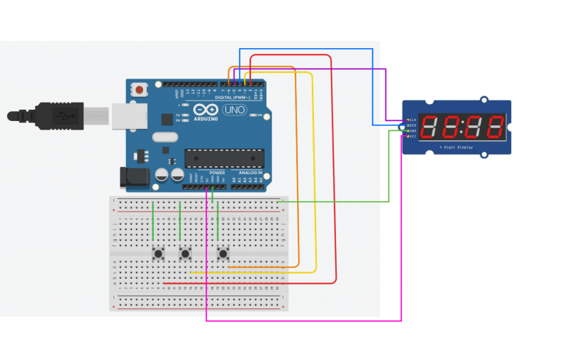
Pripojenie 7 - segmentového LED displeja k vývojovej doske, vytvorenie potrebných knižníc a funkcií. Cieľom je, aby sme dokázali zobraziť skóre futbalového zápasu, ktoré dokážeme meniť podľa potreby pomocou tlačidiel.

Literatúra:
Analýza a opis riešenia
Princíp fungovania bol jednoduchý, ak stlačíme tlačidlo príslušné k prvému tímu, meníme skóre prvého tímu a ak stlačíme tlačidlo príslušné k druhému tímu, meníme skóre druhého tímu. Takisto máme tlačidlo RESET, ktoré celé skóre resetuje. Na správne fungovanie sme si vytvorili knižnicu, v ktorej sme zadefinovali čísla od 0-9 pomocou zapnutých a vypnutých segmentov na 7 segmentovke.


Algoritmus a program
Tento program sme vytvorili na ovládanie 7 segmentového displeja pomocou tlačidiel a následného zobrazovania futbalového skóre pomocou tlačidiel. Najprv sme si vytvorili knižnicu do ktorej sme uložili čísla od 0-9 na zobrazenie čísiel pomocou svietiacich a zhasnutých segmentov. Následne sme si vytvorili funkcie na zapnutie a vypnutie komunikácie. Potom sme si vytvorili funkcie na inicializáciu, nastavenie segmentov a ich následné zobrazenie. Všetky tieto funkcie sme uložili do uart.c (resp. SemProj_uart.c).
Nakoniec sme pre INT0 a INT1 spravili funkcie, jedna pre ľavú stranu a druhá pre pravú stranu, v ktorých po stlačení tlačidla nastalo zvýšenie hodnoty o 1, kde ak sme dosiahli číslo 99 a zvýšili sme ho, číslo sa nám resetovalo naspäť na 0, keďže na číselné hodnoty sme mali iba 2 7 - segmentové displeje. Keď sme mali všetky tieto funkcie zadefinované, v hlavnej časti programu sme CLK, DIO aj všetky ostatné piny nastavili opäť ako input, povolili sme INT0 a INT1 takisto sei().
Následne vo while funkcii sme už len dané čísla, ktoré boli uložené v counter_left a counter_right zobrazovali pomocou našej funkcie pre zobrazenie čísla na 7 segmentovke, kde sme pozíciu čísel nastavili na pravú 7 segmentovku z dvojice (čiže celkovo 2. a 4. 7 segmentovka) a po zvýšení čísla na 10 a viac sa začali využívať obe 7 segmentové displeje pre daný tím. Po stlačení tlačidla RESET sa hodnoty v counter_left a counter_right vynulovali a opäť sa využívali iba pravé 7 segmentovky z dvojice. Takto to funguje donekonečna.
// Required libraries
#include <avr/io.h>
#include <util/delay.h>
#include <avr/interrupt.h>
#include "uart.h"

#define CLK  PD5  // CLK -> pin 5
#define DIO  PD4  // DIO -> pin 4


#define set_bit(ADDRESS,BIT) (ADDRESS |= (1<<BIT))
#define clear_bit(ADDRESS,BIT) (ADDRESS &= ~(1<<BIT))


#define LEFT_START_STOP_PIN PD2 // Tlacidlo pre lavy tim
#define RIGHT_START_STOP_PIN PD3 // Tlacidlo pre pravy tim
#define RESTART_PIN PD6 // Tlacidlo na vynulovanie skore


volatile uint8_t count_left = 0;  // Pocitadlo skore pre lavu dvojicu 7 segmentoviek
volatile uint8_t count_right = 0; // Pocitadlo skore pre pravu dvojicu 7 segmentoviek


// External interrupt 0 (Tlacidlo pre lavy tim)
ISR (INT0_vect)
{


    _delay_ms(10);
    if(bit_is_clear(PIND, LEFT_START_STOP_PIN)){
        // Zvysuje skore laveho time a pri dosiahnuti hodnoty 100 zresetuje hodnotu na 0
        count_left++;

        if (count_left >= 100) count_left = 0;
    }
    _delay_ms(150);
}

// External interrupt 1 (tlacidlo pre pravy tim)
ISR (INT1_vect)
{
    _delay_ms(10);
    if(bit_is_clear(PIND, RIGHT_START_STOP_PIN)){
        // Zvysuje skore praveho time a pri dosiahnuti hodnoty 100 zresetuje hodnotu na 0
        count_right++;
        if (count_right >= 100) count_right = 0;
    }
    _delay_ms(150);
}


int main(void){

    clear_bit(DDRD, CLK);  // Nastavenie CLK ako input
    set_bit(PORTD, CLK);   // CLK ako input pull-up on

    clear_bit(DDRD, DIO);  // Nastavenie DIO ako input
    set_bit(PORTD, DIO);   // DIO ako input pull-up o

    clear_bit(DDRD, LEFT_START_STOP_PIN);   // Nastavenie LEFT_START_STOP_PIN ako input
    set_bit(PORTD, LEFT_START_STOP_PIN);    // LEFT_START_STOP_PIN ako input pull-up on

    clear_bit(DDRD, RIGHT_START_STOP_PIN);  // Nastavenie RIGHT_START_STOP_PIN ako input
    set_bit(PORTD, RIGHT_START_STOP_PIN);   // RIGHT_START_STOP_PIN ako input pull-up on

	clear_bit(DDRD, RESTART_PIN);  // Nastavenie RESET_PIN ako input
	set_bit(PORTD, RESTART_PIN);  // RESET_PIN ako input pull-up on

    uint8_t data[] = { 0, 0, 0, 0 };
    set_segments(data, 4, 0);


    EIMSK = 0b00000011; // Povolenie INT0, INT1
    EICRA = 0b00001010;       // Zaznamenanie dobeznej hrany na oboch pinoch

    sei();  // Povolit prerusenia


    while (1) {
		if (bit_is_clear(PIND, RESTART_PIN)) {
			// Spusti reset

			count_left = 0; // Resetuje skore laveho timu
			count_right = 0; // Resetuje skore praveho timu

			}

			// Zobrazenie skore laveho timu na lavych 2 7 segmentovkach a skore praveho timu na pravych 2 7 segmentovkach

			display_number_segment(count_right, 0, 2, 2);

			display_number_segment(count_left, 0, 2, 0);

    }

    return 0;
}
#include <avr/io.h>
#include <util/delay.h>
#include "uart.h"

#define CLK  PD5  // CLK -> pin 5 portD.5
#define DIO  PD4  // DIO -> pin 4 portD.4

#define BIT_DELAY 100  // Delay 100ms

// Define for TM1637
#define TM1637_I2C_COMM1    0x40
#define TM1637_I2C_COMM2    0xC0
#define TM1637_I2C_COMM3    0x80

// Nastavenie cisiel na 7 segmentovom displeji
const uint8_t digitToSegment[] = {
    // XGFEDCBA
    0b00111111,    // 0
    0b00000110,    // 1
    0b01011011,    // 2
    0b01001111,    // 3
    0b01100110,    // 4
    0b01101101,    // 5
    0b01111101,    // 6
    0b00000111,    // 7
    0b01111111,    // 8
    0b01101111,    // 9
    0b01110111,    // A
    0b01111100,    // b
    0b00111001,    // C
    0b01011110,    // d
    0b01111001,    // E
    0b01110001     // F
};

uint8_t brightness = (0x7 & 0x7) | 0x08;

static const uint8_t minusSegments = 0b01000000;

int inicialize_bit(uint8_t byte){
    uint8_t data = byte;

    // 8 Data Bits
    for(uint8_t i = 0; i < 8; i++) {
        // CLK low
        set_bit(DDRD, CLK);
        clear_bit(PORTD, CLK);
        _delay_us(BIT_DELAY);

        // Set data bit
        if (data & 0x01){
            clear_bit(DDRD, DIO);  // Nastavenie DIO ako input
            set_bit(PORTD, DIO);   // DIO ako input pull-up on
        } else{
            set_bit(DDRD, DIO);    // Nastavenie DIO ako output
            clear_bit(PORTD, DIO); // Nastavenie DIO low
        }

        _delay_us(BIT_DELAY);

        // CLK high
        clear_bit(DDRD, CLK);  // Nastavenie CLK ako input
        set_bit(PORTD, CLK);   // CLK ako input pull-up on
        _delay_us(BIT_DELAY);
        data = data >> 1;
    }

    // Wait for acknowledge
    // CLK to zero
    set_bit(DDRD, CLK);     // Nastavenie CLK ako output
    clear_bit(PORTD, CLK);  // Nastavenie CLK low

    clear_bit(DDRD, DIO);   // Nastavenie DIO ako input
    set_bit(PORTD, DIO);    // DIO ako input pull-up on
    _delay_us(BIT_DELAY);

    // CLK to high
    clear_bit(DDRD, CLK);   // Nastavenie CLK ako input
    set_bit(PORTD, CLK);    // Nastavenie CLK high
    _delay_us(BIT_DELAY);
    uint8_t ack = !bit_is_clear(PIND, DIO);
    if (ack == 0)
        set_bit(DDRD, DIO);  // Nastavenie DIO ako output
    clear_bit(PORTD, DIO);  // Nastavenie DIO low

    _delay_us(BIT_DELAY);
    set_bit(DDRD, CLK);    // Nastavenie CLK ako output
    clear_bit(PORTD, CLK); // Nastavenie CLK low
    _delay_us(BIT_DELAY);

    return ack;
}


void comunication_start(){
    set_bit(DDRD, DIO);    // Nastavenie DIO ako output
    clear_bit(PORTD, DIO); // Nastavenie DIO ako output
    _delay_us(BIT_DELAY);
}

void comunication_stop(){
    set_bit(DDRD, DIO);    // Nastavenie DIO ako output
    clear_bit(PORTD, DIO); // Nastavenie DIO ako output
    _delay_us(BIT_DELAY);

    clear_bit(DDRD, CLK);  // Nastavenie CLK ako input
    set_bit(PORTD, CLK);   // CLK ako input pull-up on
    _delay_us(BIT_DELAY);

    clear_bit(DDRD, DIO);  // Nastavenie DIO ako input
    set_bit(PORTD, DIO);   // DIO ako input pull-up on
    _delay_us(BIT_DELAY);
}


void displayShowDots(uint8_t dots, uint8_t* digits){
    for(int i = 0; i < 4; ++i)
    {
        digits[i] |= (dots & 0x80);
        dots <<= 1;
    }
}


// Funkcia na zobrazenie cisla
void display_middle_dots(int num, uint8_t dots, const int leading_zero, uint8_t length, uint8_t pos){
    display_number(num < 0? -10 : 10, num < 0? -num : num, dots, leading_zero, length, pos);
}

// Funkcia na zobrazenie cisla v danom zaklade
void display_number(int8_t base, uint16_t num, uint8_t dots, const int leading_zero, uint8_t length, uint8_t pos)
{
    int negative = 0; // False
    if (base < 0) {
        base = -base;
        negative = 1; // True
    }

    uint8_t digits[4];

    if (num == 0 && !leading_zero) {
        for(uint8_t i = 0; i < (length-1); i++)
            digits[i] = 0;
        digits[length-1] = digitToSegment[0 & 0x0f];;
    }
    else {
        for(int i = length-1; i >= 0; --i)
        {
            uint8_t digit = num % base;

            if (digit == 0 && num == 0 && leading_zero == 0)
                digits[i] = 0;
            else
                digits[i] = digitToSegment[digit & 0x0f];;

            if (digit == 0 && num == 0 && negative) {
                digits[i] = minusSegments;
                negative = 0;
            }

            num /= base;
        }
    }

    if(dots != 0)
    {
        displayShowDots(dots, digits);
    }

    set_segments(digits, length, pos);
}

// Funkcia na zobrazenie cisla s default nastaveniami
void display_number_segment(int num, const int leading_zero, uint8_t length, uint8_t pos){
    display_middle_dots(num,  0x40, leading_zero, length, pos);
}

void set_segments(const uint8_t segments[], uint8_t length, uint8_t pos){
    // Zapis COMM1
    comunication_start();
    inicialize_bit(TM1637_I2C_COMM1);
    comunication_stop();

    // Zapis COMM2 + prvu cislicu adresy
    comunication_start();
    inicialize_bit(TM1637_I2C_COMM2 + (pos & 0x03));

    // Zapis datove bajty
    for (uint8_t k=0; k < length; k++)
        inicialize_bit(segments[k]);

    comunication_stop();

    // Zapis COMM3 + brightness
    comunication_start();
    inicialize_bit(TM1637_I2C_COMM3 + (brightness & 0x0f));
    comunication_stop();
}
#define set_bit(ADDRESS,BIT) (ADDRESS |= (1<<BIT))
#define clear_bit(ADDRESS,BIT) (ADDRESS &= ~(1<<BIT))

#ifndef UART_H_
#define UART_H_

void comunication_start();
void comunication_stop();
void displayShowDots(uint8_t dots, uint8_t* digits);
int inicialize_bit(uint8_t byte);
void display_middle_dots(int num, uint8_t dots, const int leading_zero, uint8_t length, uint8_t pos);
void display_number(int8_t base, uint16_t num, uint8_t dots, const int leading_zero, uint8_t length, uint8_t pos);
void display_number_segment(int num, const int leading_zero, uint8_t length, uint8_t pos);
void set_segments(const uint8_t segments[], uint8_t length, uint8_t pos);


#endif /* UART_H_ */
Zdrojový kód: zdrojaky.zip
Overenie
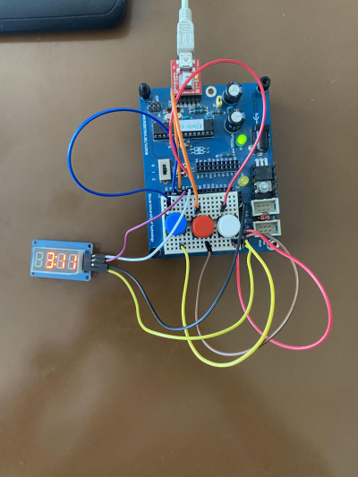
Na zobrazovanie aktuálneho skóre používame dve tlačidlá, jedným, ktorý je vľavo meníme skóre tímu vľavo, a druhým, ktorý je v strede meníme skóre tímu ktorý je napravo, posledným tlačidlom ktoré je vpravo skóre resetujeme.

Video: