ATtiny: Rozdiel medzi revíziami
Zo stránky SensorWiki
Bez shrnutí editace |
Bez shrnutí editace |
||
| (11 medziľahlých úprav od rovnakého používateľa nie je zobrazených.) | |||
| Riadok 4: | Riadok 4: | ||
* ATtiny Core library for Arduino https://github.com/SpenceKonde/ATTinyCore | * ATtiny Core library for Arduino https://github.com/SpenceKonde/ATTinyCore | ||
* Programovanie napr. cez [[USBtiny ISP]] | |||
| Riadok 21: | Riadok 23: | ||
[https://www.arduinoslovakia.eu/page/nelinearna-citlivost-ludskeho-oka Nelineárna citlivosť ľudského oka] | [https://www.arduinoslovakia.eu/page/nelinearna-citlivost-ludskeho-oka Nelineárna citlivosť ľudského oka] | ||
''' Łukasz Podkalicki''' | |||
* '''[https://blog.podkalicki.com/100-projects-on-attiny13/ 100 projektov s ATtiny]''' | |||
* [https://blog.podkalicki.com/attiny13-led-fading-with-delay-function/ LED fading effect] | |||
* [https://blog.podkalicki.com/attiny13-controlling-led-rgb-fancy-light-effects/ RGB efekty] | |||
'''SparkFun''' | '''SparkFun''' | ||
| Riadok 51: | Riadok 60: | ||
* [https://www.gadgetronicx.com/attiny85-i2c-protocol-tutorial/ I2C Master aj Slave] !!! | * [https://www.gadgetronicx.com/attiny85-i2c-protocol-tutorial/ I2C Master aj Slave] !!! | ||
* [https://www.hackster.io/alaspuresujay/use-an-attiny85-with-arduino-ide-07740c RGB demo] | * [https://www.hackster.io/alaspuresujay/use-an-attiny85-with-arduino-ide-07740c RGB demo] | ||
* [https://wiki.robotika.sk/robowiki/index.php?title=SapienIRCTL Sapien IR CTRL] Palov projekt s USB aj IR | * [https://wiki.robotika.sk/robowiki/index.php?title=SapienIRCTL Sapien IR CTRL] Palov projekt s USB aj IR | ||
* [https://www.engineersgarage.com/tutorial-8-rgb-led-interfacing-with-attiny85/ RGB Led tutorial] | * [https://www.engineersgarage.com/tutorial-8-rgb-led-interfacing-with-attiny85/ RGB Led tutorial] | ||
* '''Power save''' | |||
** rezimy su dobre opisane (aj s projektom na casovac s pipakom): http://www.technoblogy.com/show?KX0 | |||
** https://circuitdigest.com/microcontroller-projects/arduino-sleep-modes-and-how-to-use-them-to-reduce-power-consumption | |||
'''Problemy''' | '''Problemy''' | ||
* Na ake najmensie napatie to este pracuje? Bude modra LED svietit? Minimalizuj prudovu zataz. | |||
* Ked budu programovacie piny obsadene LED alebo tlacitkom tak moze byt problem, trocha sa tomu venuju tuto: https://www.kanda.com/avr-isp-circuits.html | * Ked budu programovacie piny obsadene LED alebo tlacitkom tak moze byt problem, trocha sa tomu venuju tuto: https://www.kanda.com/avr-isp-circuits.html | ||
** Alternativou moze byt UPDI Unified Program and Debug Interface (UPDI) programator, ktory pouziva len jeden pin - podobne ako DebugWire. | ** Alternativou moze byt UPDI Unified Program and Debug Interface (UPDI) programator, ktory pouziva len jeden pin - podobne ako DebugWire. | ||
| Riadok 73: | Riadok 85: | ||
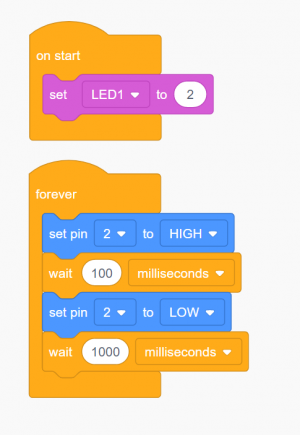
Program na jednoduché blikanie LEDkou | === '''1. Program na jednoduché blikanie LEDkou''' === | ||
<center> | |||
[[Súbor:ATtinyProgram01blockly.png|300px]]<BR> | |||
''Program v grafickom jazyku Blockly (TinkerCAD).'' | |||
</center> | |||
<tabs> | <tabs> | ||
<tab name="AVR C"><source lang="cpp"> | <tab name="AVR C"><source lang="cpp"> | ||
##define F_CPU 8000000UL // toto je lepsie vlozit do parametrov pre kompilator | |||
#include <avr/io.h> | #include <avr/io.h> | ||
#include <util/delay.h> | |||
#define LED1 PB2 // pripojena dioda | |||
#define LED1 | |||
int main(void) | int main(void) | ||
{ | { | ||
DDRB |= (1 << LED1); // set pin as OUTPUT | |||
while(1) | |||
{ | |||
PORTB |= (1<<LED1); // ... tak rozsviet LED, t.j. set PB5 na log. 1 | |||
_delay_ms(200); | |||
PORTB &= ~(1<<LED1); // zhasni LED, t.j. clear PB5 na log. 0 | |||
_delay_ms(2000); | |||
} | |||
} | } | ||
</source></tab> | </source></tab> | ||
| Riadok 106: | Riadok 131: | ||
delay(1000); // wait for a second | delay(1000); // wait for a second | ||
} | } | ||
</source></tab> | |||
<tab name="Assembler"> | |||
<source lang="asm"> | |||
/* | |||
* LED Blink s periodou 100:1000 ms | |||
* delay vygenerovane tu http://darcy.rsgc.on.ca/ACES/TEI4M/AVRdelay.html | |||
* pre frekvenciu 8 MHz (ATtiny45, internal osc.) | |||
* | |||
* LED je pripojena na pin7 (PORTB.2) | |||
*/ | |||
START: SBI DDRB,2 ; DDRB.2 = 1 (t.j. Output) | |||
LOOP: | |||
SBI PORTB,2 ; PORTB.2 = 1 (t.j. High, rozsviet LED) | |||
; CALL DELAY ; UNSUPPORTED INSTRUCTION ON ATtiny!!!! - treba nahradit RCALL + RET | |||
ldi r18, 5 ; 100ms SVIETI | |||
ldi r19, 15 | |||
ldi r20, 242 | |||
L1: dec r20 | |||
brne L1 | |||
dec r19 | |||
brne L1 | |||
dec r18 | |||
brne L1 | |||
nop | |||
CBI PORTB,2 ; PORTB.2 = 0 (t.j. Low, zhasni LED) | |||
ldi r18, 41 ; jedna seunda nesvieti (vypocet pre 8MHz!!!) | |||
ldi r19, 150 | |||
ldi r20, 128 | |||
L2: dec r20 | |||
brne L2 | |||
dec r19 | |||
brne L2 | |||
dec r18 | |||
brne L2 | |||
nop | |||
RJMP LOOP ; Skok na zaciatok (JMP nepodporovane) | |||
</source></tab> | |||
</tabs> | |||
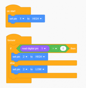
=== '''2. Tlačítko a LED''' === | |||
<center> | |||
[[Súbor:ATtinyProgram02blockly.png|300px]]<BR> | |||
''Program v grafickom jazyku Blockly (TinkerCAD).'' | |||
</center> | |||
<tabs> | |||
<tab name="Arduino"> | |||
<source lang="arduino"> | |||
#define SW1 1 | |||
#define LED1 2 | |||
void setup() | |||
{ | |||
pinMode(SW1,INPUT_PULLUP); | |||
pinMode(LED1,OUTPUT); | |||
} | |||
void loop() | |||
{ | |||
if (digitalRead(SW1) == 0) | |||
digitalWrite(LED1, HIGH); | |||
else | |||
digitalWrite(LED1, LOW); | |||
} | |||
</source></tab> | |||
<tab name="AVR C"><source lang="cpp"> | |||
#define F_CPU 8000000UL // toto je lepsie vlozit do parametrov pre kompilator | |||
#define set_bit(ADDRESS,BIT) (ADDRESS |= (1<<BIT)) | |||
#define clear_bit(ADDRESS,BIT) (ADDRESS &= ~(1<<BIT)) | |||
#include <avr/io.h> | |||
#include <util/delay.h> | |||
#define LED1 PB2 // pripojena dioda | |||
#define SW1 PB1 // pripojene tlacitko | |||
int main(void) | |||
{ | |||
DDRB |= (1 << LED1); // set LED1 pin as OUTPUT | |||
DDRB &= ~(1<<SW1); // set SW1 pin as INPUT (not necessary, default) | |||
PORTB |= (1<<SW1); // SW1 pull-up ON | |||
while(1) | |||
{ | |||
if ( bit_is_clear(PINB, SW1) ) // ak je stlacene tlacitko SW1 | |||
set_bit(PORTB,LED1); // LED1 = log.1 | |||
else // inak | |||
clear_bit(PORTB,LED1); // LED1 = log.0 | |||
} | |||
return 0; | |||
} | |||
</source></tab> | |||
<tab name="Assembler"> | |||
<source lang="asm"> | |||
/* | |||
* Program01.asm | |||
* | |||
* Ovladanie LED diody tlacitkom | |||
* Created: 16. 2. 2023 18:18:35 | |||
*/ | |||
START: SBI DDRB,2 ; DDRB.2 = 1 (t.j. Output) - LED | |||
CBI DDRB,1 ; DDRB.1 = 0 (t.j. Input) - SW1 | |||
SBI PORTB,1 ; PORTB.1 = 1 set SW1 Pull Up ON | |||
LOOP: SBI PORTB,2 ; PORTB.2 = 1 (t.j. High, rozsviet LED) | |||
ON: SBIS PINB,1 ; IF input on pin = 1 (button NOT pressed), skip next instruction | |||
RJMP ON ; otherwise just loop here | |||
CBI PORTB,2 ; PORTB.2 = 0 (t.j. Low, zhasni LED) | |||
OFF: SBIC PINB,1 ; if input on pin = 0 (button IS pressed), skip next instruction | |||
RJMP OFF ; otherwise just loop here | |||
RJMP LOOP ; Skok na LED On | |||
</source></tab> | </source></tab> | ||
</tabs> | </tabs> | ||
Aktuálna revízia z 19:15, 23. február 2023
Rychly zoznam projektov a stranok k programovaniu ATtiny (vid aj projekty DTV)
- Pighixxx Pinout diagram https://pighixxx.tumblr.com/image/93202369320
- ATtiny Core library for Arduino https://github.com/SpenceKonde/ATTinyCore
- Programovanie napr. cez USBtiny ISP
Strasne vela navodov je na strankach Roba Ulbrichta https://www.arduinoslovakia.eu/
Napriklad:
- Blik
- Tlacitko
- PWM na LEDky
- Generator zvukov
- ATtiny85 a displej TM1637
- 10-bitové PWM
- Jednoducha hracka
Nelineárna citlivosť ľudského oka
Łukasz Podkalicki
SparkFun
- ATtiny Guide
- Quick Reference Sheet - vytlacit na cvika
- RGB sviecka - blikajuce 3 RGB
- Detektor pretecenia vody na baterku CR3202 aj s modifikaciami programu
Technoblogy
- Zoznam
- Push-Button On/Off Switches
- Playing Notes on the ATtiny85
- I2C
- InfraRed Remote
Dalsie:
- Da sa programovat v Blockly cez simulator v TinkerCADe
- Vseobecne
- http://homemadehardware.com/guides/programming-an-attiny85/
- Vseobecne
- SPI Master aj Slave
- I2C Master aj Slave !!!
- RGB demo
- Sapien IR CTRL Palov projekt s USB aj IR
- RGB Led tutorial
- Power save
- rezimy su dobre opisane (aj s projektom na casovac s pipakom): http://www.technoblogy.com/show?KX0
- https://circuitdigest.com/microcontroller-projects/arduino-sleep-modes-and-how-to-use-them-to-reduce-power-consumption
Problemy
- Na ake najmensie napatie to este pracuje? Bude modra LED svietit? Minimalizuj prudovu zataz.
- Ked budu programovacie piny obsadene LED alebo tlacitkom tak moze byt problem, trocha sa tomu venuju tuto: https://www.kanda.com/avr-isp-circuits.html
- Alternativou moze byt UPDI Unified Program and Debug Interface (UPDI) programator, ktory pouziva len jeden pin - podobne ako DebugWire.
- Taky programator sa da spravit z Arduino Nano napr. https://daumemo.com/diy-updi-usb-programmer-which-can-be-made-with-cheap-hardware/
- Zakazat RESET (aby bol k dispozicii dalsi pin) nema zmysel, pretoze bez RESETu sa neda cip preprogramovat inak ako v HV programatore
Fuses
- Explain https://embedderslife.wordpress.com/2012/08/20/fuse-bits-arent-that-scary/
- https://sheepdogguides.com/arduino/attiny/fuses.htm
- https://leo.leung.xyz/wiki/ATtiny85
- http://eleccelerator.com/fusecalc/fusecalc.php?chip=attiny45&LOW=6A&LOCKBIT=FF
- https://www.engbedded.com/fusecalc/
Na koniec:
- https://github.com/MCUdude/MightyCore - moznost Arduino programovania pre ATmega16 a 32
1. Program na jednoduché blikanie LEDkou
##define F_CPU 8000000UL  // toto je lepsie vlozit do parametrov pre kompilator

#include <avr/io.h>
#include <util/delay.h>

#define LED1  PB2  // pripojena dioda

int main(void)
{
    DDRB |= (1 << LED1);  // set pin as OUTPUT

    while(1)
    {
         PORTB |=  (1<<LED1);          // ... tak rozsviet LED, t.j. set PB5 na log. 1
	     _delay_ms(200);
         PORTB &= ~(1<<LED1);         // zhasni LED, t.j. clear PB5 na log. 0
	  	 _delay_ms(2000);
    }
}
#define LEDpin 4  //aby nekolidovalo s programatorom, takto sa da trvale nechat pripojeny

void setup() {
  // initialize digital pin LED_BUILTIN as an output.
  pinMode(LEDpin, OUTPUT);
}

// the loop function runs over and over again forever
void loop() {
  digitalWrite(LEDpin, HIGH);   // turn the LED on (HIGH is the voltage level)
  delay(100);                       // wait for a second
  digitalWrite(LEDpin, LOW);    // turn the LED off by making the voltage LOW
  delay(1000);                       // wait for a second
}
/*
 *  LED Blink s periodou 100:1000 ms
 *  delay vygenerovane tu http://darcy.rsgc.on.ca/ACES/TEI4M/AVRdelay.html
 *  pre frekvenciu 8 MHz (ATtiny45, internal osc.)
 *
 *  LED je pripojena na pin7 (PORTB.2)
 */

START:	        SBI DDRB,2       ; DDRB.2 = 1 (t.j. Output)
LOOP:
		SBI PORTB,2      ; PORTB.2 = 1 (t.j. High, rozsviet LED)

;		CALL DELAY      ; UNSUPPORTED INSTRUCTION ON ATtiny!!!! - treba nahradit RCALL + RET

		ldi  r18, 5     ; 100ms SVIETI
		ldi  r19, 15
		ldi  r20, 242
L1:		dec  r20
		brne L1
		dec  r19
		brne L1
		dec  r18
		brne L1
		nop

		CBI PORTB,2     ; PORTB.2 = 0 (t.j. Low, zhasni LED)

		ldi  r18, 41    ; jedna seunda nesvieti (vypocet pre 8MHz!!!)
		ldi  r19, 150
		ldi  r20, 128
L2:		dec  r20
		brne L2
		dec  r19
		brne L2
		dec  r18
		brne L2
		nop

		RJMP LOOP		; Skok na zaciatok (JMP nepodporovane)
2. Tlačítko a LED
#define SW1  1
#define LED1 2

void setup()
{
  pinMode(SW1,INPUT_PULLUP);
  pinMode(LED1,OUTPUT);
}

void loop()
{
  if (digitalRead(SW1) == 0)
      digitalWrite(LED1, HIGH);
  else
      digitalWrite(LED1, LOW);

}
#define F_CPU 8000000UL  // toto je lepsie vlozit do parametrov pre kompilator
#define set_bit(ADDRESS,BIT) (ADDRESS |= (1<<BIT))
#define clear_bit(ADDRESS,BIT) (ADDRESS &= ~(1<<BIT))


#include <avr/io.h>
#include <util/delay.h>

#define LED1  PB2  // pripojena dioda
#define SW1   PB1  // pripojene tlacitko

int main(void)
{
    DDRB |= (1 << LED1);  // set LED1 pin as OUTPUT
	DDRB &= ~(1<<SW1);    // set SW1 pin as INPUT (not necessary, default)
	PORTB |= (1<<SW1);    // SW1 pull-up ON

    while(1)
    {
      if ( bit_is_clear(PINB, SW1) )   // ak je stlacene tlacitko SW1
 	    set_bit(PORTB,LED1);           // LED1 = log.1
      else                             // inak
	    clear_bit(PORTB,LED1);         // LED1 = log.0
    }

	return 0;
}
/*
 *	Program01.asm
 *
 *  Ovladanie LED diody tlacitkom
 *  Created: 16. 2. 2023 18:18:35
 */

START:	SBI DDRB,2       ; DDRB.2 = 1 (t.j. Output) - LED
		CBI DDRB,1       ; DDRB.1 = 0 (t.j. Input) - SW1
		SBI PORTB,1      ; PORTB.1 = 1 set SW1 Pull Up ON

LOOP:   SBI PORTB,2      ; PORTB.2 = 1 (t.j. High, rozsviet LED)
ON:     SBIS PINB,1      ; IF input on pin = 1 (button NOT pressed), skip next instruction
		RJMP ON          ; otherwise just loop here

	    CBI PORTB,2      ; PORTB.2 = 0 (t.j. Low, zhasni LED)
OFF:    SBIC PINB,1      ; if input on pin = 0 (button IS pressed),  skip next instruction
		RJMP OFF         ; otherwise just loop here

		RJMP LOOP		 ; Skok na LED On

