MEMS cvičenie 2: Rozdiel medzi revíziami
Zo stránky SensorWiki
Bez shrnutí editace |
dBez shrnutí editace |
||
| (16 medziľahlých úprav od rovnakého používateľa nie je zobrazených.) | |||
| Riadok 1: | Riadok 1: | ||
Poznamky 2020: https://www.qsl.net/om3cph/sw/pot.html https://electronics.stackexchange.com/questions/231522/improving-the-linearity-of-a-potentiometer-after-loading | Poznamky 2020: https://www.qsl.net/om3cph/sw/pot.html https://electronics.stackexchange.com/questions/231522/improving-the-linearity-of-a-potentiometer-after-loading | ||
http://www.geofex.com/article_folders/potsecrets/potscret.htm | http://www.geofex.com/article_folders/potsecrets/potscret.htm | ||
-- | |||
Poznamky 2022: https://stackoverflow.com/questions/7091294/how-to-build-a-lookup-table-in-c-sdcc-compiler-with-linear-interpolation | |||
Na tomto cvičení je cieľom pripojiť odporový senzor k Arduinu a vylepšiť jeho prevodovú charakteristiku vybranou metódou a zlinearizovanú hodnotu zobraziť | |||
na nejakom miestnom displeji (LED, LCD a pod.) prípadne ju odoslať po sériovej linke do PC (v simulátore TinkerCAD). | |||
== Potenciometrické snímače == | == Potenciometrické snímače == | ||
| Riadok 18: | Riadok 22: | ||
* Príklad na pripojenie analógového senzora: http://senzor.robotika.sk/sensorwiki/index.php/Acrob007 | * Príklad na pripojenie analógového senzora: http://senzor.robotika.sk/sensorwiki/index.php/Acrob007 | ||
* Arduino homepage https://www.arduino.cc/ | * Arduino homepage https://www.arduino.cc/ | ||
Na pridanie do TinkerCAD triedy (classroom) použite [https://www.tinkercad.com/joinclass/B5ZT5MYJJNZP tento link]. Ak od vás program pýta vstupný kód, je to B5ZT5MYJJNZP | |||
<html> | |||
<iframe width="725" height="453" src="https://www.tinkercad.com/embed/6Pg8q4b7Kst?editbtn=1" frameborder="0" marginwidth="0" marginheight="0" scrolling="no"></iframe> | |||
</html> | |||
Ak sa vám nezobrazuje vložený simulátor správne, použite prosím, [https://www.tinkercad.com/things/6Pg8q4b7Kst tento link]. | |||
<!-- Note to self: generovane linky z TinkerCADu expiruju po 336 hodinach - 14 dni --> | |||
<source lang="cpp"> | <source lang="cpp"> | ||
#define mySensor 0 // 0: potenciometer | |||
#define | // 3: senzor sily | ||
// 5: senzor ohybu | |||
int adcValue; | int adcValue; | ||
| Riadok 27: | Riadok 44: | ||
void setup() | void setup() | ||
{ | { // monitor sa otvara dole vpravo | ||
Serial.begin(9600); // | Serial.begin(9600); // typicke rychlosti su 9600 alebo 115200 | ||
} | } | ||
void loop() | void loop() | ||
{ | { | ||
adcValue = analogRead(mySensor); // read ADC value | |||
outputValue = adcValue; | |||
Serial.println(outputValue); // prints value over serial | |||
delay(100); // delay in milliseconds | |||
delay(100); | |||
} | } | ||
</source> | </source> | ||
Lepší kód na poloautomatické meranie | |||
<source lang="cpp"> | |||
// Meranie na potenciometrickej doske v.2024 | |||
// Tlacitko je na A5 a zapiseme nim meranie | |||
// Potenciometer je na A4 a da sa citat 0/1023 | |||
// pricom ak zmenim prepinacom charakteristiku, tak | |||
// tym ze je to napatovy delic, funguje stale rovnako | |||
unsigned long int sensorValue; | |||
unsigned int counter; | |||
void setup() | |||
{ | |||
Serial.begin(115200); | |||
pinMode(LED_BUILTIN, OUTPUT); | |||
pinMode(18, INPUT); | |||
pinMode(19, INPUT); | |||
Serial.println("*** MISA measurement (press Red PB to start): ***\n\n"); | |||
counter = 1; | |||
} | } | ||
void loop() { | void loop() | ||
{ | |||
digitalWrite(13,HIGH); // Led ON = Ready | |||
while ( digitalRead(19)== 1) | |||
{/* wait here */} | |||
digitalWrite(13,LOW); // Led OFF = Measuring... | |||
/* odmeraj N hodnot a vypocitaj priemer */ | |||
sensorValue = 0; | |||
for ( int i=1; i<=64; i++) | |||
sensorValue += analogRead(A4); | |||
sensorValue = sensorValue / 64; | |||
Serial.print(counter++); | |||
Serial.print(","); | |||
Serial.println(sensorValue); | |||
delay(500); // delay in between reads for stability | |||
} | } | ||
| Riadok 199: | Riadok 112: | ||
</source> | </source> | ||
== Linearizácia prevodovej charakteristiky == | |||
=== 1. Look-up table === | |||
<source lang="cpp"> | |||
#include <avr/pgmspace.h> | |||
const PROGMEM int table[] = {11,12,15,...}; | |||
return( table[adcValue] ); | |||
</source> | |||
Viac info tu: https://www.arduino.cc/en/Reference/PROGMEM | |||
== | === 2. Po častiach lineárna náhrada === | ||
=== | <source lang="cpp"> | ||
/* segment 1 */ | |||
if (adcValue > x0) && (adcValue <= x1) | |||
y = k1 * adcValue + q1; | |||
/* segment 2 */ | |||
if (adcValue > x1) && (adcValue <= x2) | |||
y = k2 * adcValue + q2; | |||
* | |||
return(y) | |||
</source> | </source> | ||
Dá sa použiť aj funkcia map v Arduine - https://www.arduino.cc/reference/en/language/functions/math/map/ | |||
=== 3. Aproximácia funkcie === | |||
<source lang="cpp"> | |||
y = a2 * adcValue^2 + a1 * adcValue + a0; | |||
return(y); | |||
</source> | </source> | ||
* | * http://terpconnect.umd.edu/~toh/spectrum/CurveFitting.html | ||
* https://www.gnu.org/software/octave/doc/interpreter/Polynomial-Interpolation.html | |||
* http://octave.sourceforge.net/optim/function/leasqr.html | |||
* http://octave.sourceforge.net/optim/function/expfit.html | |||
* https://www.gnu.org/software/gsl/manual/html_node/Example-programs-for-Nonlinear-Least_002dSquares-Fitting.html | |||
* https://www.gnu.org/software/octave/doc/interpreter/One_002ddimensional-Interpolation.html#One_002ddimensional-Interpolation | |||
| Riadok 319: | Riadok 178: | ||
* Graf 2: chybové krivky (viď obr.) | * Graf 2: chybové krivky (viď obr.) | ||
* Program pre mikroprocesor na linearizáciu | * Program pre mikroprocesor na linearizáciu | ||
* Porovnať namerané výsledky s predošlými | |||
[[Súbor:Example2-1.png|500px]] | [[Súbor:Example2-1.png|500px]] | ||
Hodnotenie: 5 | Hodnotenie: 5 bodov | ||
Deadline: <FONT COlor="red">''' | Deadline: <FONT COlor="red">'''8. 3. 2022 '''</font> | ||
Aktuálna revízia z 09:01, 21. február 2025
Poznamky 2020: https://www.qsl.net/om3cph/sw/pot.html https://electronics.stackexchange.com/questions/231522/improving-the-linearity-of-a-potentiometer-after-loading http://www.geofex.com/article_folders/potsecrets/potscret.htm
Poznamky 2022: https://stackoverflow.com/questions/7091294/how-to-build-a-lookup-table-in-c-sdcc-compiler-with-linear-interpolation
Na tomto cvičení je cieľom pripojiť odporový senzor k Arduinu a vylepšiť jeho prevodovú charakteristiku vybranou metódou a zlinearizovanú hodnotu zobraziť na nejakom miestnom displeji (LED, LCD a pod.) prípadne ju odoslať po sériovej linke do PC (v simulátore TinkerCAD).
Potenciometrické snímače
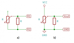
- Poskladajte si odporový senzor polohy so stupnicou (ak nemáte, použite senzor v TinkerCADe).
- Zmerajte prevodovú charakteristiku odporového senzora polohy pomocou ohmmetra (cvičenie 1).
- Senzor pripojte k A/D prevodníku mikropočítača a pomocou programu nižšie zmerajte prevodovú charakteristiku celého meracieho člena.
- Prevodovú charakteristiku zlinearizujte a doložte úspešnosť porovnaním metrologických parametrov.

- Príklad na pripojenie analógového senzora: http://senzor.robotika.sk/sensorwiki/index.php/Acrob007
- Arduino homepage https://www.arduino.cc/
Na pridanie do TinkerCAD triedy (classroom) použite tento link. Ak od vás program pýta vstupný kód, je to B5ZT5MYJJNZP
Ak sa vám nezobrazuje vložený simulátor správne, použite prosím, tento link.
#define mySensor 0            // 0: potenciometer
                              // 3: senzor sily
                              // 5: senzor ohybu

int adcValue;
float outputValue;

void setup()
{                              // monitor sa otvara dole vpravo
 Serial.begin(9600);           // typicke rychlosti su 9600 alebo 115200
}

void loop()
{
  adcValue = analogRead(mySensor); // read ADC value

  outputValue = adcValue;

  Serial.println(outputValue);        // prints value over serial

 delay(100);                       // delay in milliseconds

}
Lepší kód na poloautomatické meranie
// Meranie na potenciometrickej doske v.2024
// Tlacitko je na A5 a zapiseme nim meranie
// Potenciometer je na A4 a da sa citat 0/1023
//   pricom ak zmenim prepinacom charakteristiku, tak
//   tym ze je to napatovy delic, funguje stale rovnako

unsigned long int sensorValue;
unsigned      int counter;

void setup()
{
  Serial.begin(115200);

  pinMode(LED_BUILTIN, OUTPUT);
  pinMode(18, INPUT);
  pinMode(19, INPUT);

  Serial.println("*** MISA measurement (press Red PB to start): ***\n\n");
  counter = 1;
}

void loop()
{
  digitalWrite(13,HIGH);  // Led ON = Ready
  while ( digitalRead(19)== 1)
     {/* wait here */}

  digitalWrite(13,LOW);  // Led OFF = Measuring...

  /* odmeraj N hodnot a vypocitaj priemer */
  sensorValue = 0;
    for ( int i=1; i<=64; i++)
      sensorValue += analogRead(A4);
  sensorValue = sensorValue / 64;

  Serial.print(counter++);
  Serial.print(",");
  Serial.println(sensorValue);

  delay(500);        // delay in between reads for stability

}
Linearizácia prevodovej charakteristiky
1. Look-up table
 #include <avr/pgmspace.h>

 const PROGMEM int table[] = {11,12,15,...};

 return( table[adcValue] );
Viac info tu: https://www.arduino.cc/en/Reference/PROGMEM
2. Po častiach lineárna náhrada
  /* segment 1 */
 if (adcValue > x0) && (adcValue <= x1)
   y = k1 * adcValue + q1;

  /* segment 2 */
if (adcValue > x1) && (adcValue <= x2)
   y = k2 * adcValue + q2;

 return(y)
Dá sa použiť aj funkcia map v Arduine - https://www.arduino.cc/reference/en/language/functions/math/map/
3. Aproximácia funkcie
   y = a2 * adcValue^2 + a1 * adcValue + a0;
   return(y);
- https://www.gnu.org/software/octave/doc/interpreter/Polynomial-Interpolation.html
- http://octave.sourceforge.net/optim/function/leasqr.html
- http://octave.sourceforge.net/optim/function/expfit.html
- https://www.gnu.org/software/gsl/manual/html_node/Example-programs-for-Nonlinear-Least_002dSquares-Fitting.html
- https://www.gnu.org/software/octave/doc/interpreter/One_002ddimensional-Interpolation.html#One_002ddimensional-Interpolation
Úlohy
Úlohy, ktoré treba odovzdať:
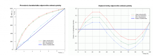
- Graf 1: prevodové charakteristiky
- Chyby podľa EN 60 770
- Nepresnosť
- Meraná chyba
- Nelinearita
- Hysteréza
- Neopakovateľnosť
- Graf 2: chybové krivky (viď obr.)
- Program pre mikroprocesor na linearizáciu
- Porovnať namerané výsledky s predošlými
Hodnotenie: 5 bodov
Deadline: 8. 3. 2022
