Zbernica i2c: MCP4725: Rozdiel medzi revíziami
Zo stránky SensorWiki
Bez shrnutí editace |
Bez shrnutí editace |
||
| (Jedna medziľahlá úprava od rovnakého používateľa nie je zobrazená.) | |||
| Riadok 10: | Riadok 10: | ||
'''Literatúra:''' | '''Literatúra:''' | ||
* [https://ww1.microchip.com/downloads/en/devicedoc/22039d.pdf Katalógový list čipu MCP4725] | * [https://ww1.microchip.com/downloads/en/devicedoc/22039d.pdf Katalógový list čipu MCP4725] | ||
* [https://ww1.microchip.com/downloads/en/DeviceDoc/Atmel-7810-Automotive-Microcontrollers-ATmega328P_Datasheet.pdf Katalógový list čipu ATmega328P] | |||
* [https://github.com/RobTillaart/MCP4725 Arduino knižnica k MCP4725] | * [https://github.com/RobTillaart/MCP4725 Arduino knižnica k MCP4725] | ||
| Riadok 72: | Riadok 73: | ||
<tabs> | <tabs> | ||
<tab name="MCP4725 Example"><source lang="c" style="background: LightYellow;"> | <tab name="MCP4725 Driver Example"><source lang="c" style="background: LightYellow;"> | ||
/* | /* | ||
* MicroProject.c | * MicroProject.c | ||
Aktuálna revízia z 13:09, 7. jún 2023
Záverečný projekt predmetu MIPS / LS2023 - Kristián Greif
Zadanie
Vytvorte jednoduchý driver pre 12-bitový D/A prevodník MCP4725 s I2C zbernicou a EEPROM - zápis požadovanej hodnoty do registra a EEPROM, čítanie aktuálne nastavenej/uloženej hodnoty.
Literatúra:
Analýza a opis riešenia
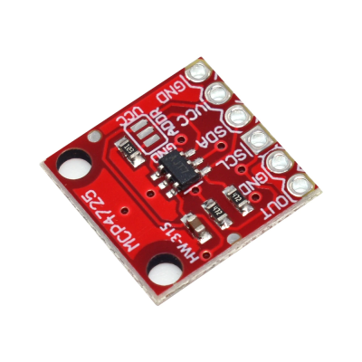
MCP4725
MCP4725 je digitálno-analógový prevodník, ktorý nám umožní premeniť 12-bitový číslicový vstup (0-4095) na korešpondujúcu hodnotu jednosmerného napätia, v rámci rozsahu napájania (0-5V). Komunikuje pomocou I2C.
Opis riešenia
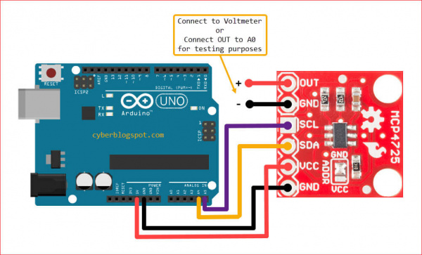
Najskôr sme k vývojovej doske Arduino Uno pripojili plošný spoj s D/A prevodníkom MCP4725, ako je zobrazené na obrázku či v schéme zapojenia - prevodník komunikuje pomcou I2C protokolu, teda potrebuje dva vodiče na uskutočnčnie prenosu dát a napájanie. Adresa prevodníka na I2C zbernici je prednastavená výrobcom na 0x60.
Na výstupe OUT sa vždy objaví naprogramované napätie, v rozsahu napájania, teda 0-5V - tento výstup sme kvôli demonštrácii pripojili na analógový vstup A0 na Arduine, aby sme mohli neskôr túto hodnotu sledovať priamo v mikroprocesore a mohli tak neskôr vykresliť porovnanie časových priebehov veličín.
Na základe katalógového listu D/A prevodníka, sme v programe vytvorili jednoduché rutiny na komunikáciu s prevodníkom cez I2C:
- zápis požadovanej hodnoty do registra D/A prevodníka (a EEPROM)
- zápis hodnoty len priamo do DAC registra
- rýchly
- hneď zmení analógový výstup prevodníka
- hodnota sa po resete nezachová, prepíše sa na poslednú hodnotu uloženú v EEPROM
- zápis hodnoty do DAC registra a zároveň EEPROM
- pomerne pomalý (typ. 25-50ms)
- takmer hneď zmení analógový výstup prevodníka
- hodnota sa po resete zachová - pri štarte sa prepíše DAC register touto hodnotou
- zápis hodnoty len priamo do DAC registra
- čítanie nastavenej hodnoty z registra D/A prevodníka (a EEPROM)
Na uskutočnenie I2C komunikácie sme použili štandardnú knižnicu pre I2C komunikáciu, podobne ako pre UART komunikíciu.
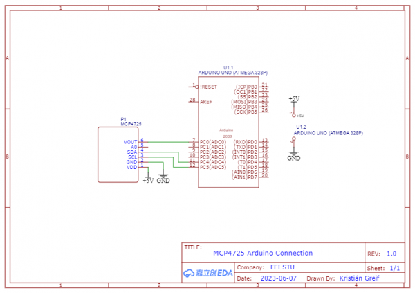
Schéma zapojenia
Schéma zapojenia použitého D/A prevodníka k vývojovej doske Arduino Uno:
Algoritmus a program
- Demonštračný program: MCP4725_Example.c
- Inicializácia všetkých použitých periférií
- Po štarte sa na výstup D/A automatický zapíše posledná hodnota z EEPROM (Power-On-Reset)
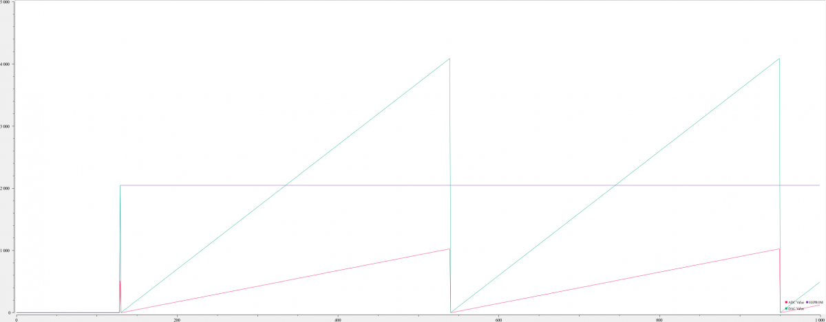
- Zapíšeme do DAC registra a EEPROM novú hodnotu - 2048 - polovicu z rozsahu
- V hlavnom cykle čítame hodnotu výstupu z D/A prevodníka cez A/D prevodník, hodnotu zapísanú v EEPROM a aktuálnu hodnotu v DAC registri
- Postupne zvyšujeme výstupné napätie D/A prevodníka - zápisom 12b hodnoty do DAC registra - dosiahnutím maxima sa hodnota resetuje na minimum
- Prečítané hodnoty vypíšeme cez UART - zobrazíme ako časový priebeh v aplikácii SerialPlot
- Knižnica s rutinami pre komunikáciu s D/A prevodníkom: MCP4725.c, MCP4725.h
- Podrobnejší opis rutín v komentároch kódu
- Knižnica pre I2C komunikáciu: i2cmaster.c, i2cmaster.h
- Knižnica pre UART komunikáciu: uart.c, uart.h
/*
 * MicroProject.c
 *
 * MCP4725 I2C DAC Simple Driver Example
 *
 * Created: 6. 5. 2023 13:55:04
 * Author : greif
 */

// Includes
#include <stdio.h>
#include <avr/io.h>
#include "uart.h" // UART for SerialPlot output

#define DAC_ADDR 0x60 // MCP4725 address - if not set here, default address is 0x60
#include "mcp4725.h" // MCP4725 Simple Driver


FILE uart_stream = FDEV_SETUP_STREAM(uart_putc, uart_getc, _FDEV_SETUP_RW); // Link UART functions


// ADC initialization
void adc_init(void){
	ADMUX = (0<<REFS1)|(1<<REFS0); // AVCC - set the ADC reference voltage
	ADCSRA = (1<<ADEN) // "Turn ON" the ADC
	|(1<<ADPS2)|(1<<ADPS1)|(1<<ADPS0); // Set the prescaler - fOsc/128, fADC = 125kHz, conversion duration < 0,1ms, align right
}


// Read ADC channel
uint16_t adc_read(uint8_t a_pin){
	a_pin &= 0x07;
	ADMUX = (ADMUX & 0xF8)|a_pin; // Set the channel

	ADCSRA |= (1<<ADSC); // Start the conversion
	while(ADCSRA & (1<<ADSC)); // Wait until conversion done

	return (ADC);
}


int main(void)
{
	DACInit(); // Initialize the MCP4725 12b DAC on the I2C bus

	adc_init(); // Initialize the on-board 10b ADC

	// Initialize UART communication
	uart_init();
	stdout = stdin = &uart_stream;
	printf("Ready to start...\n\n");

	setDACValue(2048, 1); // Write a 12b (0-4095) value to DAC register and EEPROM

	// Gradually increase MCP4725 output, while displaying measured voltage (ADC reading) and MCP4725 register/EEPROM readings
	uint16_t i = 0;
    while (1)
    {
		uint16_t adcValue = adc_read(0); // Get ADC reading from the MCP4725 output pin
		uint16_t eeprom = readEEPROM(); // Read current EEPROM value from MCP4725 (persistent)
		uint16_t current = readDACValue(); // Read current DAC register value from MCP_4725 (temporary)

		// Reset counter if out of MCP4725 12b range
 		if(i > DAC_MAX){
			 i = DAC_MIN;
		}

		setDACValue(i, 0); // Write a 12b (0-4095) value to DAC register - without writing the EEPROM
		i+=10; // Increase the counter

		printf("%u %u %u\r\n", adcValue, eeprom, current); // Send measured values to UART (SerialPlot)
    }

	return 0;
}
/*
 * mcp4725.c
 *
 * Simple MCP725 12b I2C DAC Driver
 *
 * Created: 5. 6. 2023 10:51:34
 *  Author: greif
 */

#include "mcp4725.h"
#include "i2cmaster.h" // Standard I2C library


#define DAC_REG_WRITE 0x40 // Write mode - DAC register only, EEPROM unchanged
#define DAC_EEPROM_REG_WRITE 0x60 // // Write mode - both DAC register and EEPROM
#define DAC_RESET 0x06 // MCP4725 reset command (general call)


// Perform internal MCP4725 reset - EEPROM data uploaded to the DAC register
void resetDAC(){
	i2c_start_wait( (DAC_ADDR << 1) | I2C_WRITE); // Start I2C communication with MCP4725 (ack polling), write mode
	i2c_write(0x00); // Start address 0x00 (I2C general call)
	i2c_write(DAC_RESET); // Send reset command
	i2c_stop(); // Stop I2C communication
}


// Initialize MCP4725
void DACInit(){
	i2c_init(); // initialize the I2C library
	resetDAC(); // Issue a general call reset after power-on (recommended by manufacturer - in case the automatic power-on reset did not work)
}


/* Write MCP4725 register
*
* Parameters:
*	const uint16_t value - 12b value representing output voltage
*	const int EEPROM - write mode:
*		if true, value is written to both DAC register and EEPROM - slow
*		if false, value is written only to the DAC register - fast
*/
void writeDAC(const uint16_t value, const int EEPROM){
	i2c_start_wait( (DAC_ADDR << 1) | I2C_WRITE); // Start I2C communication with MCP4725 (ack polling), write mode
	i2c_write(EEPROM ? DAC_EEPROM_REG_WRITE : DAC_REG_WRITE); // Set write address depending on write mode (parameter)
	i2c_write((value & 0xFF0) >> 4); // Write upper data bits (D11, D10, D9, D8, D7, D6, D5, D4)
	i2c_write((value & 0xF) << 4); // Write Lower data bits (D3, D2, D1, D0)
	i2c_stop(); // Stop I2C communication
}


/* Read MCP4725 register
*
* Parameters:
*	uint8_t *buffer - buffer pointer to store read bits
*	const uint8_t length - buffer length
*/
void readDACRegister(uint8_t *buffer, const uint8_t length){
	i2c_start_wait( (DAC_ADDR << 1) | I2C_WRITE); // Start I2C communication with MCP4725 (ack polling), write mode
	i2c_write(0x00); // Set the address to the start (0x00)

	i2c_rep_start( (DAC_ADDR << 1) | I2C_READ ); // Start I2C communication with MCP4725 again, this time in read mode

	// Read (length-1) bits from the register
	uint8_t counter = 0;
	while (counter < length-1){
		buffer[counter++] = i2c_readAck(); // Read the bit, continue requesting data
	}
	buffer[counter] = i2c_readNak(); // Read the last wanted bit, do not request any other data

	i2c_stop(); // Stop I2C communication
}


// Check if writing to the EEPROM has finished
int DACReady(){
	uint8_t buffer[1];
	readDACRegister(buffer, 1); // Read the first byte
	return ((buffer[0] & 0x80) > 0); // Return the status of the first bit
}


// Read the set value form MCP4725 EEPROM
uint16_t readEEPROM(){
	while(!DACReady()); // Wait until writing to the EEPROM is finished

	uint8_t buffer[5];
	readDACRegister(buffer, 5); // Read 5 bytes (EEPROM data in the 4-5th byte)

	// Convert read bytes to the actual set 12b value
	uint16_t result = buffer[3] & 0x0F;
	result = result << 8;
	result = result + buffer[4];

	return result;
}


// Read the set value from MCP4725 DAC register
uint16_t readDACValue(){
	while(!DACReady()); // Wait until writing to the EEPROM is finished

	uint8_t buffer[3];
	readDACRegister(buffer, 3); // Read 3 bytes (DAC data in the 2-3th byte)

	// Convert read bytes to the actual set 12b value
	uint16_t result = buffer[1];
	result = result << 4;
	result = result + (buffer[2] >> 4);

	return result;
}


/* Set MCP4725 value
* Wrapper of void writeDAC(const uint16_t value, const int EEPROM)
* Added input range check
*
* Parameters:
*	const uint16_t value - 12b value representing output voltage
*	const int persistent - write mode:
*		if true, value is written to both DAC register and EEPROM - slow, value stays unchanged after reset
*		if false, value is written only to the DAC register - fast, value changes after reset - to the EEPROM value
*
* Return:
*	1 if value out of range
*	0 if write successful
*/
int setDACValue(uint16_t value, const int persistent){
	// Check the input range
	if(value < DAC_MIN || value > DAC_MAX){
		return 1;
	}

	while(!DACReady()); // Wait until writing to the EEPROM is finished
	writeDAC(value, persistent); // Depending on the write mode, write the value to MCP4725

	return 0;
}
/*
 * mcp4725.h
 *
 * Simple MCP725 12b I2C DAC Driver
 *
 * Created: 5. 6. 2023 10:52:00
 *  Author: greif
 */


#ifndef MCP4725_H_
#define MCP4725_H_

#include <stdio.h>


#ifndef F_CPU
#define F_CPU 16000000UL
#endif

// If not defined otherwise, set the MCP4725 address to 0x60
#ifndef DAC_ADDR
#define DAC_ADDR 0x60
#endif


// Define MCP4725 range (12b)
#define DAC_MIN 0
#define DAC_MAX 4095


void resetDAC();
void DACInit();
void writeDAC(const uint16_t value, const int EEPROM);
void readDACRegister(uint8_t *buffer, const uint8_t length);
int DACReady();
uint16_t readEEPROM();
uint16_t readDACValue();
int setDACValue(uint16_t value, const int persistent);


#endif /* MCP4725_H_ */
#include "uart.h"
#include <avr/io.h>
#include <util/setbaud.h>


void uart_init( void )
{
	UBRR0H = UBRRH_VALUE;
	UBRR0L = UBRRL_VALUE;

	#if USE_2X
	UCSR0A |= _BV(U2X0);
	#else
	UCSR0A &= ~(_BV(U2X0));
	#endif

	UCSR0C = _BV(UCSZ01) | _BV(UCSZ00); /* 8-bit data */
	UCSR0B = _BV(RXEN0) | _BV(TXEN0);   /* Enable RX and TX */
}


void uart_putc(char c)
{
	if (c == '\n')
	{
		uart_putc('\r');
	}
	loop_until_bit_is_set(UCSR0A, UDRE0); /* Wait until data register empty. */
	UDR0 = c;
}


void uart_puts(const char *s)
{
	/* toto je vasa uloha */
	int i = 0;
	while(s[i] != '\0'){
		uart_putc(s[i]);
		i++;
	}
}

char uart_getc(void) {
	loop_until_bit_is_set(UCSR0A, RXC0); /* Wait until data exists. */
	return UDR0;
}
/* ************************************************************************* */
/* FileName          : uart.h                                              */
/* ************************************************************************* */

#ifndef F_CPU
#define F_CPU 16000000UL
#endif

#define BAUD 9600

void uart_init( void );

void uart_putc( char c );
void uart_puts( const char *s );

char uart_getc( void );
/*************************************************************************
* Title:    I2C master library using hardware TWI interface
* Author:   Peter Fleury <pfleury@gmx.ch>  http://jump.to/fleury
* File:     $Id: twimaster.c,v 1.4 2015/01/17 12:16:05 peter Exp $
* Software: AVR-GCC 3.4.3 / avr-libc 1.2.3
* Target:   any AVR device with hardware TWI
* Usage:    API compatible with I2C Software Library i2cmaster.h
**************************************************************************/
#include <inttypes.h>
#include <compat/twi.h>

#include "i2cmaster.h"


/* define CPU frequency in hz here if not defined in Makefile */
#ifndef F_CPU
#define F_CPU 16000000UL
#endif

/* I2C clock in Hz */
#define SCL_CLOCK  100000L


/*************************************************************************
 Initialization of the I2C bus interface. Need to be called only once
*************************************************************************/
void i2c_init(void)
{
  /* initialize TWI clock: 100 kHz clock, TWPS = 0 => prescaler = 1 */

  TWSR = 0;                         /* no prescaler */
  TWBR = ((F_CPU/SCL_CLOCK)-16)/2;  /* must be > 10 for stable operation */

}/* i2c_init */


/*************************************************************************
  Issues a start condition and sends address and transfer direction.
  return 0 = device accessible, 1= failed to access device
*************************************************************************/
unsigned char i2c_start(unsigned char address)
{
    uint8_t   twst;

	// send START condition
	TWCR = (1<<TWINT) | (1<<TWSTA) | (1<<TWEN);

	// wait until transmission completed
	while(!(TWCR & (1<<TWINT)));

	// check value of TWI Status Register. Mask prescaler bits.
	twst = TW_STATUS & 0xF8;
	if ( (twst != TW_START) && (twst != TW_REP_START)) return 1;

	// send device address
	TWDR = address;
	TWCR = (1<<TWINT) | (1<<TWEN);

	// wail until transmission completed and ACK/NACK has been received
	while(!(TWCR & (1<<TWINT)));

	// check value of TWI Status Register. Mask prescaler bits.
	twst = TW_STATUS & 0xF8;
	if ( (twst != TW_MT_SLA_ACK) && (twst != TW_MR_SLA_ACK) ) return 1;

	return 0;

}/* i2c_start */


/*************************************************************************
 Issues a start condition and sends address and transfer direction.
 If device is busy, use ack polling to wait until device is ready

 Input:   address and transfer direction of I2C device
*************************************************************************/
void i2c_start_wait(unsigned char address)
{
    uint8_t   twst;


    while ( 1 )
    {
	    // send START condition
	    TWCR = (1<<TWINT) | (1<<TWSTA) | (1<<TWEN);

    	// wait until transmission completed
    	while(!(TWCR & (1<<TWINT)));

    	// check value of TWI Status Register. Mask prescaler bits.
    	twst = TW_STATUS & 0xF8;
    	if ( (twst != TW_START) && (twst != TW_REP_START)) continue;

    	// send device address
    	TWDR = address;
    	TWCR = (1<<TWINT) | (1<<TWEN);

    	// wail until transmission completed
    	while(!(TWCR & (1<<TWINT)));

    	// check value of TWI Status Register. Mask prescaler bits.
    	twst = TW_STATUS & 0xF8;
    	if ( (twst == TW_MT_SLA_NACK )||(twst ==TW_MR_DATA_NACK) )
    	{
    	    /* device busy, send stop condition to terminate write operation */
	        TWCR = (1<<TWINT) | (1<<TWEN) | (1<<TWSTO);

	        // wait until stop condition is executed and bus released
	        while(TWCR & (1<<TWSTO));

    	    continue;
    	}
    	//if( twst != TW_MT_SLA_ACK) return 1;
    	break;
     }

}/* i2c_start_wait */


/*************************************************************************
 Issues a repeated start condition and sends address and transfer direction

 Input:   address and transfer direction of I2C device

 Return:  0 device accessible
          1 failed to access device
*************************************************************************/
unsigned char i2c_rep_start(unsigned char address)
{
    return i2c_start( address );

}/* i2c_rep_start */


/*************************************************************************
 Terminates the data transfer and releases the I2C bus
*************************************************************************/
void i2c_stop(void)
{
    /* send stop condition */
	TWCR = (1<<TWINT) | (1<<TWEN) | (1<<TWSTO);

	// wait until stop condition is executed and bus released
	while(TWCR & (1<<TWSTO));

}/* i2c_stop */


/*************************************************************************
  Send one byte to I2C device

  Input:    byte to be transfered
  Return:   0 write successful
            1 write failed
*************************************************************************/
unsigned char i2c_write( unsigned char data )
{
    uint8_t   twst;

	// send data to the previously addressed device
	TWDR = data;
	TWCR = (1<<TWINT) | (1<<TWEN);

	// wait until transmission completed
	while(!(TWCR & (1<<TWINT)));

	// check value of TWI Status Register. Mask prescaler bits
	twst = TW_STATUS & 0xF8;
	if( twst != TW_MT_DATA_ACK) return 1;
	return 0;

}/* i2c_write */


/*************************************************************************
 Read one byte from the I2C device, request more data from device

 Return:  byte read from I2C device
*************************************************************************/
unsigned char i2c_readAck(void)
{
	TWCR = (1<<TWINT) | (1<<TWEN) | (1<<TWEA);
	while(!(TWCR & (1<<TWINT)));

    return TWDR;

}/* i2c_readAck */


/*************************************************************************
 Read one byte from the I2C device, read is followed by a stop condition

 Return:  byte read from I2C device
*************************************************************************/
unsigned char i2c_readNak(void)
{
	TWCR = (1<<TWINT) | (1<<TWEN);
	while(!(TWCR & (1<<TWINT)));

    return TWDR;

}/* i2c_readNak */
#ifndef I2CMASTER_H_
#define I2CMASTER_H_


#ifndef _I2CMASTER_H
#define _I2CMASTER_H
/*************************************************************************
* Title:    C include file for the I2C master interface
*           (i2cmaster.S or twimaster.c)
* Author:   Peter Fleury <pfleury@gmx.ch>
* File:     $Id: i2cmaster.h,v 1.12 2015/09/16 09:27:58 peter Exp $
* Software: AVR-GCC 4.x
* Target:   any AVR device
* Usage:    see Doxygen manual
**************************************************************************/

/**
 @file
 @defgroup pfleury_ic2master I2C Master library
 @code #include <i2cmaster.h> @endcode

 @brief I2C (TWI) Master Software Library

 Basic routines for communicating with I2C slave devices. This single master
 implementation is limited to one bus master on the I2C bus.

 This I2c library is implemented as a compact assembler software implementation of the I2C protocol
 which runs on any AVR (i2cmaster.S) and as a TWI hardware interface for all AVR with built-in TWI hardware (twimaster.c).
 Since the API for these two implementations is exactly the same, an application can be linked either against the
 software I2C implementation or the hardware I2C implementation.

 Use 4.7k pull-up resistor on the SDA and SCL pin.

 Adapt the SCL and SDA port and pin definitions and eventually the delay routine in the module
 i2cmaster.S to your target when using the software I2C implementation !

 Adjust the  CPU clock frequence F_CPU in twimaster.c or in the Makfile when using the TWI hardware implementaion.

 @note
    The module i2cmaster.S is based on the Atmel Application Note AVR300, corrected and adapted
    to GNU assembler and AVR-GCC C call interface.
    Replaced the incorrect quarter period delays found in AVR300 with
    half period delays.

 @author Peter Fleury pfleury@gmx.ch  http://tinyurl.com/peterfleury
 @copyright (C) 2015 Peter Fleury, GNU General Public License Version 3

 @par API Usage Example
  The following code shows typical usage of this library, see example test_i2cmaster.c

 @code

 #include <i2cmaster.h>


 #define Dev24C02  0xA2      // device address of EEPROM 24C02, see datasheet

 int main(void)
 {
     unsigned char ret;

     i2c_init();                             // initialize I2C library

     // write 0x75 to EEPROM address 5 (Byte Write)
     i2c_start_wait(Dev24C02+I2C_WRITE);     // set device address and write mode
     i2c_write(0x05);                        // write address = 5
     i2c_write(0x75);                        // write value 0x75 to EEPROM
     i2c_stop();                             // set stop conditon = release bus


     // read previously written value back from EEPROM address 5
     i2c_start_wait(Dev24C02+I2C_WRITE);     // set device address and write mode

     i2c_write(0x05);                        // write address = 5
     i2c_rep_start(Dev24C02+I2C_READ);       // set device address and read mode

     ret = i2c_readNak();                    // read one byte from EEPROM
     i2c_stop();

     for(;;);
 }
 @endcode

*/


/**@{*/

#if (__GNUC__ * 100 + __GNUC_MINOR__) < 304
#error "This library requires AVR-GCC 3.4 or later, update to newer AVR-GCC compiler !"
#endif

#include <avr/io.h>

/** defines the data direction (reading from I2C device) in i2c_start(),i2c_rep_start() */
#define I2C_READ    1

/** defines the data direction (writing to I2C device) in i2c_start(),i2c_rep_start() */
#define I2C_WRITE   0


/**
 @brief initialize the I2C master interace. Need to be called only once
 @return none
 */
extern void i2c_init(void);


/**
 @brief Terminates the data transfer and releases the I2C bus
 @return none
 */
extern void i2c_stop(void);


/**
 @brief Issues a start condition and sends address and transfer direction

 @param    addr address and transfer direction of I2C device
 @retval   0   device accessible
 @retval   1   failed to access device
 */
extern unsigned char i2c_start(unsigned char addr);


/**
 @brief Issues a repeated start condition and sends address and transfer direction

 @param   addr address and transfer direction of I2C device
 @retval  0 device accessible
 @retval  1 failed to access device
 */
extern unsigned char i2c_rep_start(unsigned char addr);


/**
 @brief Issues a start condition and sends address and transfer direction

 If device is busy, use ack polling to wait until device ready
 @param    addr address and transfer direction of I2C device
 @return   none
 */
extern void i2c_start_wait(unsigned char addr);


/**
 @brief Send one byte to I2C device
 @param    data  byte to be transfered
 @retval   0 write successful
 @retval   1 write failed
 */
extern unsigned char i2c_write(unsigned char data);


/**
 @brief    read one byte from the I2C device, request more data from device
 @return   byte read from I2C device
 */
extern unsigned char i2c_readAck(void);

/**
 @brief    read one byte from the I2C device, read is followed by a stop condition
 @return   byte read from I2C device
 */
extern unsigned char i2c_readNak(void);

/**
 @brief    read one byte from the I2C device

 Implemented as a macro, which calls either @ref i2c_readAck or @ref i2c_readNak

 @param    ack 1 send ack, request more data from device<br>
               0 send nak, read is followed by a stop condition
 @return   byte read from I2C device
 */
extern unsigned char i2c_read(unsigned char ack);
#define i2c_read(ack)  (ack) ? i2c_readAck() : i2c_readNak();


/**@}*/
#endif


#endif /* I2CMASTER_H_ */
Zdrojový kód: MCP4725_Source.zip
Overenie
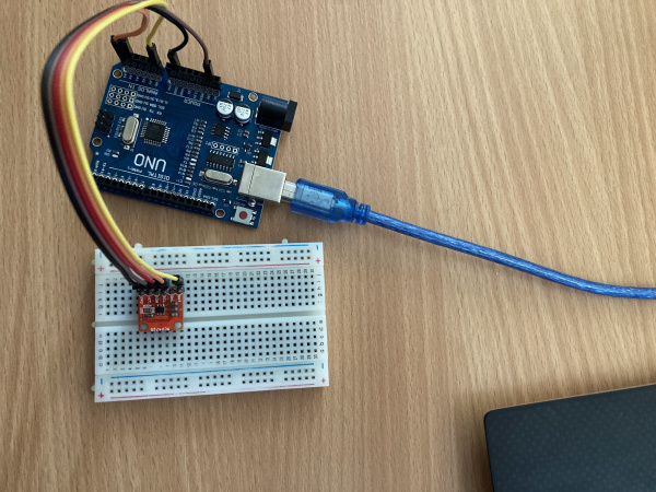
Na overenie funkčnosti knižnice stačí samotný plošný spoj s MCP4725 prevodníkom a Arduino UNO pripojené k počítaču cez USB port. Postup používania je opísaný v sekcii Analýza a opis riešenia.
Reálne zapojenie
Demonštrácia riešenia
Na obrázku je prostredie aplikácie SerialPlot, ktorá vykresľuje hodnotu zapísanú v DAC registri, EEPROM a hodnotu výstupu D/A prevodníka čítanú interným A/D prevodníkom.
Video: