AVR Example T1 counter: Rozdiel medzi revíziami
Zo stránky SensorWiki
Bez shrnutí editace |
Bez shrnutí editace |
||
| (Jedna medziľahlá úprava od rovnakého používateľa nie je zobrazená.) | |||
| Riadok 5: | Riadok 5: | ||
iny terminal aby sa to pekne vypisovalo: | iny terminal aby sa to pekne vypisovalo: | ||
<source lang="c"> | |||
<tabs> | |||
<tab name="Arduino"><source lang="c"> | |||
#define SWITCH 5 // select the pin for Switch | #define SWITCH 5 // select the pin for Switch | ||
| Riadok 30: | Riadok 32: | ||
} | } | ||
</source> | </source></tab> | ||
</tabs> | |||
| Riadok 39: | Riadok 42: | ||
[[Obrázok:AVR Timer TCNT1 Counter.png|center]] | [[Obrázok:AVR Timer TCNT1 Counter.png|center]] | ||
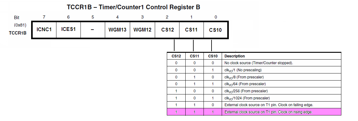
Nasledovny kus programu nastavi pocitadlo na 5 impulzov pred pretecenim (0xFFFF - 5) a | |||
potom sleduje v hlavnej slucke, kedy nastane pretecenie. Ako hodinky je pouzity externy | |||
signal na T1, cize tlacitko alebo 555. | |||
<source lang="C"> | |||
/* Example 9.2. Timer counter 1 in timer mode - pooled version */ | |||
#define SWITCH 5 // Arduino D5, ATmega328 PD.5 | |||
#define LED 13 // Arduino D13, ATmega328 PB.5 | |||
int ledState = LOW; // variable used to store the last LED status, to toggle the light | |||
void setup() // run once, when the sketch starts | |||
{ | |||
/* *********************** Init device ************************************ */ | |||
pinMode(SWITCH, INPUT); // this pin is an INPUT | |||
pinMode(LED, OUTPUT); | |||
Serial.begin(9600); | |||
Serial.println("Timer T1 test:"); | |||
TCCR1B = 0x07; // T1 clk = external clock source on pin T1, rising edge | |||
TCCR1A = 0x00; // T1 in timer mode | |||
TCNT1 = 0xFFFB; // initialize the counter (16-bit! Low+High bytes) | |||
TIFR1 = 0x01; // (1<<TOV1); if a 1 is written to a TOV1 bit | |||
// - the TOV1 bit will be cleared | |||
} | |||
/* *********************** Main Loop ************************************** */ | |||
void loop() // run over and over again | |||
{ | |||
if ( (TIFR1 & 0x01) == 0x01) // If the overflow flag is set | |||
{ | |||
ledState = !ledState; // toggle the status of the ledPin | |||
digitalWrite(LED, ledState); // update the LED pin itself | |||
TCNT1 = 0xFFFB; // Restart T1 - reload | |||
TIFR1 = 0x01; // Clear the overflow flag | |||
} | |||
else | |||
asm("nop"); // Do nothing | |||
Serial.print("Input D5 = "); | |||
Serial.print(digitalRead(SWITCH),BIN); | |||
Serial.print(" TCNT1 = "); | |||
Serial.print(TCNT1,DEC); | |||
Serial.print('\r'); // this will not work with embedded Serial Monitor, | |||
// but works fine with e.g. putty terminal | |||
} | |||
</source> | |||
Aktuálna revízia z 17:48, 21. február 2021
Tento program pouzije D5 (arduino) ako pocitadlo. Mozne pripojit tlacitko, alebo 555 a pocitat pocet impulzov.
Vstavany terminal Arduina nema formatovanie, takze treba pouzit iny terminal aby sa to pekne vypisovalo:
#define SWITCH 5                // select the pin for Switch

void setup()
{
 pinMode(SWITCH, INPUT);        // this pin is an INPUT
  TCNT1 = 0x00;                 // initialize (CLEAR)counter
 TCCR1B = 0x07;                 // T1 clk = external clock source on pin T1, rising edge

 Serial.begin(9600);
 Serial.println("Button test:");
}

void loop()                      // endless loop
{
 Serial.print("Input D5 = ");
 Serial.print(digitalRead(SWITCH),BIN);
 Serial.print("  TCNT1 = ");
 Serial.print(TCNT1,DEC);
 Serial.print('\r');             // this will not work with embedded Serial Monitor,
                                 // but works fine with e.g. putty terminal

 delay(250);                     // wait 1/4s for another measurement
}


Nasledovny kus programu nastavi pocitadlo na 5 impulzov pred pretecenim (0xFFFF - 5) a
potom sleduje v hlavnej slucke, kedy nastane pretecenie. Ako hodinky je pouzity externy
signal na T1, cize tlacitko alebo 555.
/* Example 9.2. Timer counter 1 in timer mode - pooled version  */

#define SWITCH 5      // Arduino D5, ATmega328 PD.5
#define LED 13        // Arduino D13, ATmega328 PB.5

int ledState = LOW;         // variable used to store the last LED status, to toggle the light

void setup()                    // run once, when the sketch starts
{
  /* *********************** Init device ************************************ */

 pinMode(SWITCH, INPUT);        // this pin is an INPUT
 pinMode(LED, OUTPUT);

 Serial.begin(9600);
 Serial.println("Timer T1 test:");

 TCCR1B = 0x07;       // T1 clk = external clock source on pin T1, rising edge
 TCCR1A = 0x00;       // T1 in timer mode
  TCNT1 = 0xFFFB;     // initialize the counter (16-bit! Low+High bytes)
  TIFR1 = 0x01;       // (1<<TOV1);   if a 1 is written to a TOV1 bit
                      //              - the TOV1 bit will be cleared
}

  /* *********************** Main Loop ************************************** */

void loop()                          // run over and over again
{
      if ( (TIFR1 & 0x01) == 0x01)   // If the overflow flag is set
      {
        ledState = !ledState;        // toggle the status of the ledPin
        digitalWrite(LED, ledState); // update the LED pin itself
        TCNT1 = 0xFFFB;              // Restart T1 - reload
        TIFR1 = 0x01;                // Clear the overflow flag
       }
      else
        asm("nop");                  // Do nothing

   Serial.print("Input D5 = ");
   Serial.print(digitalRead(SWITCH),BIN);
   Serial.print("  TCNT1 = ");
   Serial.print(TCNT1,DEC);
   Serial.print('\r');             // this will not work with embedded Serial Monitor,
                                 // but works fine with e.g. putty terminal

}