AVR Vstupy a výstupy v C: Rozdiel medzi revíziami
Z SensorWiki
| Riadok 1: | Riadok 1: | ||
| − | |||
== Vstupy a výstupy na MiniMEXLE doske. == | == Vstupy a výstupy na MiniMEXLE doske. == | ||
| Riadok 19: | Riadok 18: | ||
<source lang="c"> | <source lang="c"> | ||
| − | + | #include <avr\io.h> | |
| − | |||
| − | |||
| − | |||
| − | |||
| − | |||
| − | |||
| − | |||
| − | |||
| − | |||
| − | |||
| − | |||
| − | |||
| − | |||
| − | #include <avr\io.h> | ||
| − | |||
| − | |||
| − | |||
| − | |||
| − | + | #define SW1 0 | |
| + | #define SW2 1 | ||
| + | #define SW3 2 | ||
| + | #define SW4 3 | ||
| − | + | #define RedLED 5 | |
| − | + | int main(void) { | |
| − | |||
| − | /* | + | /* *********************** Init device MiniMEXLE ******************************** */ |
| − | + | DDRB = 0b00000100; // PORTB LED on PB2 is output, PB6, 7 IN!!! | |
| − | + | PORTB = 0b00000100; // LED Active low, LED off, No pull-ups | |
| + | DDRC = 0b00100000; // PORTC LED on PC5 is output, SW1-4 are inputs | ||
| + | PORTC = 0b00001111; // LED Active high, LED off, pull-ups ON | ||
| + | DDRD = 0b10000000; // PORTD bit 7 is output, pull-ups OFF | ||
| + | PORTD = 0b00000000; // PORTD bit PD7 is switch common ground | ||
| − | |||
| + | for (;;) { | ||
| + | if( !( PINC & 0b00000001) ) { | ||
| + | // if( !( PINC & (1<<0) ) ) { | ||
| + | // if( bit_is_clear(PINC, 0) ) { | ||
| + | PORTB &= 0b11111011; // Yellow LED ON | ||
| + | while (!( PINC&0x01) ); // Wait until not released | ||
| + | } | ||
| + | |||
| + | if(bit_is_clear(PINC, 1)){ | ||
| + | PORTB |= 0b00000100; // Yellow LED OFF | ||
| + | loop_until_bit_is_set(PINC, 1); | ||
| + | } | ||
| − | + | if(bit_is_clear(PINC, SW3)){ | |
| + | PORTC |= 0b00100000; // Red LED ON | ||
| + | // PORTC |= _BV(PC5); | ||
| + | // PORTC |= (1<<RedLED); | ||
| + | // PORTC |= (1<<5); | ||
| + | loop_until_bit_is_set(PINC, SW3); | ||
| + | } | ||
| − | + | if(bit_is_clear(PINC, SW4)) { | |
| − | + | PORTC &= 0b11011111; // Red LED OFF | |
| − | + | // PORTC &= ~(_BV(PC5)); | |
| − | + | // PORTC &= ~(1<<RedLED); | |
| − | // | + | // PORTC &= ~(1<<5); |
| − | + | loop_until_bit_is_set(PINC, SW4); | |
| + | } | ||
| + | } | ||
| − | |||
| − | |||
} | } | ||
| − | |||
</source> | </source> | ||
| − | |||
| − | |||
| − | |||
| − | |||
| − | |||
[[Category:AVR]][[Category:CAD_RS]] | [[Category:AVR]][[Category:CAD_RS]] | ||
Verzia zo dňa a času 13:48, 26. november 2008
Vstupy a výstupy na MiniMEXLE doske.
Obvykle sa pri programovaní jednočipových mikropočítačov začína programom na ovládanie jedného vstupu a výstupu, napr. tlačítko a LED. Je to taký "Hello, World!" program pre vnorené systémy.
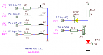
Na doske MiniMEXLE máme dve LED diódy a štryi tlačítka.
Tlačítka S1 až S4 sú pripojené k pinom PC0 až PC3 a sú aktívne v nule, žltá LED je pripojená k PB2 a je tiež aktívna v nule (t.j. LED svieti, keď je na výstupe log. 0). Druhá, červená LED dióda je aktívna v jednotke a je pripojená na pin PC5.
Nasledovný C-program demonštruje možnosti prístupu k binárnym vstupom a výstupom
rôznymi prostriedkami jazyka avr-gcc.
#include <avr\io.h>

#define SW1 0
#define SW2 1
#define SW3 2
#define SW4 3

#define RedLED 5

int main(void) {

  /* *********************** Init device MiniMEXLE ******************************** */

    DDRB = 0b00000100;       // PORTB LED on PB2  is output, PB6, 7 IN!!!
   PORTB = 0b00000100;       // LED Active low, LED off, No pull-ups

    DDRC = 0b00100000;       // PORTC LED on PC5  is output, SW1-4 are inputs
   PORTC = 0b00001111;       // LED Active high, LED off, pull-ups ON

    DDRD = 0b10000000;       // PORTD bit 7 is output, pull-ups OFF
   PORTD = 0b00000000;       // PORTD bit PD7 is switch common ground


for (;;) {
		      if( !( PINC & 0b00000001) ) {
		   // if( !( PINC & (1<<0) ) )    {
		   // if( bit_is_clear(PINC, 0) ) {
                PORTB &= 0b11111011;     // Yellow LED ON
                while (!( PINC&0x01) );  // Wait until not released
                }

		   if(bit_is_clear(PINC, 1)){
                PORTB |= 0b00000100;     // Yellow LED OFF
                loop_until_bit_is_set(PINC, 1);
                }

           if(bit_is_clear(PINC, SW3)){
                   PORTC |= 0b00100000;     // Red LED ON
				// PORTC |= _BV(PC5);
				// PORTC |= (1<<RedLED);
				// PORTC |= (1<<5);
                loop_until_bit_is_set(PINC, SW3);
                }

           if(bit_is_clear(PINC, SW4)) {
                   PORTC &= 0b11011111;     // Red LED OFF
				// PORTC &= ~(_BV(PC5));
				// PORTC &= ~(1<<RedLED);
				// PORTC &= ~(1<<5);
                loop_until_bit_is_set(PINC, SW4);
                }
          }

}
