7-segmentový displej na futbal
Zo stránky SensorWiki
Záverečný projekt predmetu MIPS / LS2024 - Daniel Žula
Zadanie
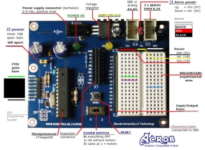
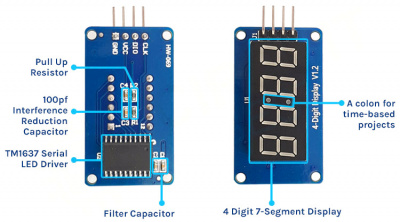
Pripojenie 7 - segmentového LED displeja k vývojovej doske, vytvorenie potrebných knižníc a funkcií. Cieľom je, aby sme dokázali zobraziť skóre futbalového zápasu, ktoré dokážeme meniť podľa potreby pomocou tlačidiel.

Literatúra:
Analýza a opis riešenia
Princíp fungovania bol jednoduchý, ak stlačíme tlačidlo príslušné k prvému tímu, meníme skóre prvého tímu a ak stlačíme tlačidlo príslušné k druhému tímu, meníme skóre druhého tímu. Takisto máme tlačidlo RESET, ktoré celé skóre resetuje. Na správne fungovanie sme si vytvorili knižnicu, v ktorej sme zadefinovali čísla od 0-9 pomocou zapnutých a vypnutých segmentov na 7 segmentovke.

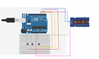
Nezabudnite doplniť schému zapojenia!

Algoritmus a program
Algoritmus programu je....
#include <avr/io.h>

#define F_CPU 16000000UL  // Define CPU frequency

// Required libraries
#include <stdio.h>
#include <avr/io.h>
#include <util/delay.h>
#include <avr/interrupt.h>


#define set_bit(ADDRESS,BIT) (ADDRESS |= (1<<BIT))
#define clear_bit(ADDRESS,BIT) (ADDRESS &= ~(1<<BIT))

#define CLK  PD5  // CLK -> pin 5 portD.5
#define DIO  PD4  // DIO -> pin 4 portD.4

#define LEFT_START_STOP_PIN PD2 // Left team score button
#define RIGHT_START_STOP_PIN PD3 // Right team score button
#define RESTART_PIN PD6 // Restart button

#define BIT_DELAY 100  // Delay 100ms

// Define for TM1637
#define TM1637_I2C_COMM1    0x40
#define TM1637_I2C_COMM2    0xC0
#define TM1637_I2C_COMM3    0x80

// 7-segment display digit mapping
const uint8_t digitToSegment[] = {
    // XGFEDCBA
    0b00111111,    // 0
    0b00000110,    // 1
    0b01011011,    // 2
    0b01001111,    // 3
    0b01100110,    // 4
    0b01101101,    // 5
    0b01111101,    // 6
    0b00000111,    // 7
    0b01111111,    // 8
    0b01101111,    // 9
    0b01110111,    // A
    0b01111100,    // b
    0b00111001,    // C
    0b01011110,    // d
    0b01111001,    // E
    0b01110001     // F
};

static const uint8_t minusSegments = 0b01000000;

uint8_t brightness = (0x7 & 0x7) | 0x08;


void comunication_start(){
    set_bit(DDRD, DIO);    // Set DIO as output
    clear_bit(PORTD, DIO); // Set DIO as output
    _delay_us(BIT_DELAY);
}

void comunication_stop(){
    set_bit(DDRD, DIO);    // Set DIO as output
    clear_bit(PORTD, DIO); // Set DIO as output
    _delay_us(BIT_DELAY);

    clear_bit(DDRD, CLK);  // Set CLK as input
    set_bit(PORTD, CLK);   // CLK as input pull-up on
    _delay_us(BIT_DELAY);

    clear_bit(DDRD, DIO);  // Set DIO as input
    set_bit(PORTD, DIO);   // DIO as input pull-up on
    _delay_us(BIT_DELAY);
}

int inicialize_bit(uint8_t byte){
    uint8_t data = byte;

    // 8 Data Bits
    for(uint8_t i = 0; i < 8; i++) {
        // CLK low
        set_bit(DDRD, CLK);
        clear_bit(PORTD, CLK);
        _delay_us(BIT_DELAY);

        // Set data bit
        if (data & 0x01){
            clear_bit(DDRD, DIO);  // Set DIO as input
            set_bit(PORTD, DIO);   // DIO as input pull-up on
        } else{
            set_bit(DDRD, DIO);    // Set DIO as output
            clear_bit(PORTD, DIO); // Set DIO low
        }

        _delay_us(BIT_DELAY);

        // CLK high
        clear_bit(DDRD, CLK);  // Set CLK as input
        set_bit(PORTD, CLK);   // CLK as input pull-up on
        _delay_us(BIT_DELAY);
        data = data >> 1;
    }

    // Wait for acknowledge
    // CLK to zero
    set_bit(DDRD, CLK);     // Set CLK as output
    clear_bit(PORTD, CLK);  // Set CLK low

    clear_bit(DDRD, DIO);   // Set DIO as input
    set_bit(PORTD, DIO);    // DIO as input pull-up on
    _delay_us(BIT_DELAY);

    // CLK to high
    clear_bit(DDRD, CLK);   // Set CLK as input
    set_bit(PORTD, CLK);    // Set CLK high
    _delay_us(BIT_DELAY);
    uint8_t ack = !bit_is_clear(PIND, DIO);
    if (ack == 0)
        set_bit(DDRD, DIO);  // Set DIO as output
    clear_bit(PORTD, DIO);  // Set DIO low

    _delay_us(BIT_DELAY);
    set_bit(DDRD, CLK);    // Set CLK as output
    clear_bit(PORTD, CLK); // Set CLK low
    _delay_us(BIT_DELAY);

    return ack;
}

void displayShowDots(uint8_t dots, uint8_t* digits){
    for(int i = 0; i < 4; ++i)
    {
        digits[i] |= (dots & 0x80);
        dots <<= 1;
    }
}

void set_segments(const uint8_t segments[], uint8_t length, uint8_t pos){
    // Write COMM1
    comunication_start();
    inicialize_bit(TM1637_I2C_COMM1);
    comunication_stop();

    // Write COMM2 + first digit address
    comunication_start();
    inicialize_bit(TM1637_I2C_COMM2 + (pos & 0x03));

    // Write the data bytes
    for (uint8_t k=0; k < length; k++)
        inicialize_bit(segments[k]);

    comunication_stop();

    // Write COMM3 + brightness
    comunication_start();
    inicialize_bit(TM1637_I2C_COMM3 + (brightness & 0x0f));
    comunication_stop();
}


// Function to display a number in a given base with custom options
void display_number(int8_t base, uint16_t num, uint8_t dots, const int leading_zero,
                              uint8_t length, uint8_t pos)
{
    int negative = 0; // False
    if (base < 0) {
        base = -base;
        negative = 1; // True
    }

    uint8_t digits[4];

    if (num == 0 && !leading_zero) {
        // Singular case - take care separately
        for(uint8_t i = 0; i < (length-1); i++)
            digits[i] = 0;
        digits[length-1] = digitToSegment[0 & 0x0f];;
    }
    else {
        for(int i = length-1; i >= 0; --i)
        {
            uint8_t digit = num % base;

            if (digit == 0 && num == 0 && leading_zero == 0)
                // Leading zero is blank
                digits[i] = 0;
            else
                digits[i] = digitToSegment[digit & 0x0f];;

            if (digit == 0 && num == 0 && negative) {
                digits[i] = minusSegments;
                negative = 0;
            }

            num /= base;
        }
    }

    if(dots != 0)
    {
        displayShowDots(dots, digits);
    }

    set_segments(digits, length, pos);
}

// Function to display a middle dots
void display_middle_dots(int num, uint8_t dots, const int leading_zero,
                            uint8_t length, uint8_t pos){
    display_number(num < 0? -10 : 10, num < 0? -num : num, dots, leading_zero, length, pos);
}

// Function to display a decimal number with default options
void display_number_segment(int num, const int leading_zero, uint8_t length, uint8_t pos){
    display_middle_dots(num,  0x40, leading_zero, length, pos);
}

volatile uint8_t count_left = 0;  // Counter for the left displays
volatile uint8_t count_right = 0; // Counter for the right displays


// External interrupt 0 (button for the left team)
ISR (INT0_vect)
{


    _delay_ms(10);
    if(bit_is_clear(PIND, LEFT_START_STOP_PIN)){
        // Increase left count and reset if it reaches 100
        count_left++;

        if (count_left >= 100) count_left = 0;
    }
    _delay_ms(150);
}

// External interrupt 1 (button for the right team)
ISR (INT1_vect)
{
    _delay_ms(10);
    if(bit_is_clear(PIND, RIGHT_START_STOP_PIN)){
        // Increase right count and reset if it reaches 100
        count_right++;
        if (count_right >= 100) count_right = 0;
    }
    _delay_ms(150);
}


int main(void){

    clear_bit(DDRD, CLK);  // Set CLK as input
    set_bit(PORTD, CLK);   // CLK as input pull-up on

    clear_bit(DDRD, DIO);  // Set DIO as input
    set_bit(PORTD, DIO);   // DIO as input pull-up o

    clear_bit(DDRD, LEFT_START_STOP_PIN);   // Set LEFT_START_STOP_PIN as input
    set_bit(PORTD, LEFT_START_STOP_PIN);    // LEFT_START_STOP_PIN as input pull-up on

    clear_bit(DDRD, RIGHT_START_STOP_PIN);  // Set RIGHT_START_STOP_PIN as input
    set_bit(PORTD, RIGHT_START_STOP_PIN);   // RIGHT_START_STOP_PIN as input pull-up on

	clear_bit(DDRD, RESTART_PIN);  // set RESET_PIN as input
	set_bit(PORTD, RESTART_PIN);  // RESET_PIN as input pull-up on

    uint8_t data[] = { 0, 0, 0, 0 };
    set_segments(data, 4, 0);


    EIMSK = 0b00000011; // Enable INT0, INT1
    EICRA = 0b00001010;       // Detect falling edge on both pins

    sei();  // Enable interrupts

    set_bit(DDRB, PB5);

    while (1) {
		if (bit_is_clear(PIND, RESTART_PIN)) {
			// Perform reset operation

			count_left = 0; // Reset the left count
			count_right = 0; // Reset the right count

			}

			// Display left count on left two displays and right count on right two displays

			display_number_segment(count_right, 0, 2, 2);

			display_number_segment(count_left, 0, 2, 0);

    }

    return 0;
}
Pridajte sem aj zbalený kompletný projekt, napríklad takto (použite jednoznačné pomenovanie, nemôžeme mať na serveri 10x zdrojaky.zip:
Zdrojový kód: zdrojaky.zip
Overenie
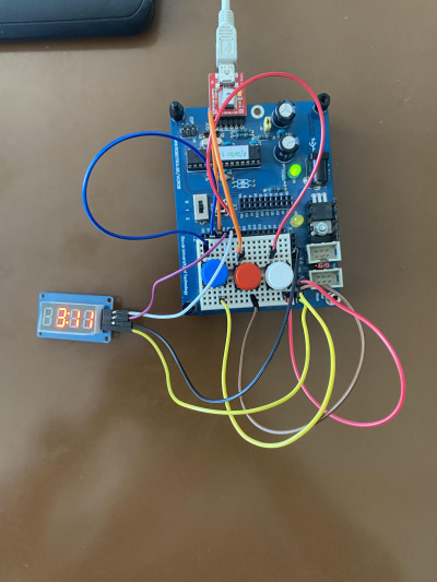
Na zobrazovanie aktuálneho skóre používame dve tlačidlá, jedným, ktorý je vľavo meníme skóre tímu vľavo, a druhým, ktorý je v strede meníme skóre tímu ktorý je napravo, posledným tlačidlom ktoré je vpravo skóre resetujeme.

Video:
Kľúčové slová 'Category', ktoré sú na konci stránky nemeňte.